dispersion-shifted fibers (original) (raw)
Definition: fibers with a non-standard zero dispersion wavelength
Categories:  fiber optics and waveguides,
  lightwave communications,
  light pulses
- dispersion-engineered fibers
- dispersion-shifted fibers
- dispersion-flattened fibers
- dispersion-decreasing fibers
Related: Dispersion Engineering for Telecom Fiberschromatic dispersiontelecom fibersfiberswavelength division multiplexingspecialty fibers
Page views in 12 months: 1348
DOI: 10.61835/c9p Cite the article: BibTex BibLaTex plain textHTML Link to this page! LinkedIn
Content quality and neutrality are maintained according to our editorial policy.
📦 For purchasing dispersion-shifted fibers, use the RP Photonics Buyer's Guide — an expert-curated directory for finding all relevant suppliers, which also offers advanced purchasing assistance.
Contents
What are Dispersion-shifted Fibers?
Standard telecom fibers exhibit zero chromatic dispersion in the 1.3-μm wavelength region. This was convenient for early optical fiber communications systems, which often operated around 1310 nm. However, the 1.5-μm region later became more important because the fiber losses are lower there, and erbium-doped fiber amplifiers (EDFAs) are available for this region (whereas 1.3-μm amplifiers do not reach comparable performance). In this wavelength region, however, standard single-mode fibers (now sometimes called dispersion-unshifted fibers) exhibit significant anomalous dispersion. For linear transmission, this can be a problem because it leads to significant dispersive pulse broadening, limiting the achievable transmission rates or distances.
Therefore, some special fiber types with substantially modified dispersion characteristics have been developed, where one utilizes modified waveguide dispersion resulting from a modified refractive index profile of the core. In particular, there are dispersion-shifted fibers [11] and dispersion-flattened fibers with much reduced dispersion slope. A review paper [9] gives a detailed history of the developments.
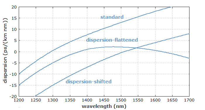
Figure 1: Approximate chromatic dispersion for different types of telecom fibers.
Dispersion-shifted Fibers with Substantial Dispersion Slope
An ordinary step-index single-mode fiber has its zero dispersion wavelength around 1.3 μm — only slightly longer than the zero dispersion wavelength of fused silica — and substantially anomalous dispersion around 1.5 μm. The first approach was to develop fiber designs where the zero dispersion wavelength is shifted into the 1.5-μm region, i.e., close to the used signal wavelengths. Essentially, one requires increased waveguide dispersion of the normal type.
The original attempt was to simply modify the parameters of the step-index design: use a smaller core in conjunction with rather high numerical aperture to roughly preserve the V-number. While this was successful in terms of shifting the dispersion, the propagation losses of such fibers turned out to be rather high. Initially, the reason for that was not fully clear, as the loss increase was larger than expected. It turned out that mechanical stress at the core–cladding interface (here, with a large GeO2 concentration difference) played an important role.

Designing Dispersion-modified Fibers
For working out such designs, considering a number of trade-offs, you need a very flexible simulation tool. The RP Fiber Power software is ideal for such work.
Therefore, researchers started to investigate designs of graded-index fibers, i.e., with a gradual variation of the germania concentration and thus the refractive index. A common type of index profile was of the form n(r) = n_\textrm{c} (1 - 2 \Delta (r / a)^{\alpha})^{0.5}$$
which for the most common value ($\alpha = 1$) is called triangular, although precisely speaking it is not exactly triangular due to the power of 0.5. (What is triangular is actually ($n^2(r)$), which is the dielectric constant ($\epsilon$), but for the typically small values of ($\Delta$), that difference is not substantial.) Modified variants of that profile have the index peak in the center capped and/or use another index step where the triangular portion ends, for example. With such designs, it became possible to shift the zero dispersion wavelength without significantly increasing the propagation losses, and also with maintaining robust single-mode guidance.
Concerning telecom applications, the original idea was to minimize chromatic dispersion at the signal wavelengths. However, it turned out that zero chromatic dispersion is not necessarily ideal for data transmission. Particularly for the transmission of multiple channels (→ wavelength division multiplexing), four-wave mixing effects can be phase-matched and thus introduce significant distortions, if the dispersion is too weak. Therefore, it can be advantageous to use non-zero dispersion-shifted fibers [12], which are designed to have a moderate amount of group velocity dispersion (GVD) in the wavelength range of the data transmission, with the zero dispersion wavelength lying somewhat outside this region. There are different versions:
- NZD+ fibers have their zero dispersion wavelength at 1510 nm and anomalous dispersion at the typical signal wavelengths (longer than 1510 nm).
- NZD− fibers have a zero dispersion wavelength of 1580 nm, resulting in normal dispersion at the signal wavelengths.
Dispersion-shifted fibers still have a substantial positive dispersion slope (specified with units of ps/(nm2 km)), i.e., their group velocity dispersion in (fs2/m) decreases with increasing wavelength, or increases with decreasing optical frequency. That implies positive third-order dispersion (TOD).
Often, the effective mode area of dispersion-shifted fibers is smaller than for an ordinary single-mode fiber. This can be detrimental, e.g. in terms of a required higher precision in the fusion splicing of fibers, increased splice losses when connecting ordinary and dispersion-shifted fibers, and increased nonlinear optical effects. Therefore, the effective mode area should be considered as one of the important design goals, but there are certain trade-offs.

Dispersion Engineering for Telecom Fibers
We explore different ways of optimizing refractive index profile for specific chromatic dispersion properties of telecom fibers, resulting in dispersion-shifted or dispersion-flattened fibers. This also involves automatic optimizations.
Dispersion-flattened Fibers
The above-mentioned dispersion slope can be a problem, particularly in wavelength division multiplexing, where different signals experience substantially different GVD values. Even when only a single signal wavelength is used, it is inconvenient that the dispersion slope strongly restricts the usable wavelength range. Therefore, dispersion-flattened fibers with a much reduced dispersion slope have been developed. They can, for example, exhibit near zero dispersion or some moderate relatively constant amount of GVD in the telecom C band. Their fabrication tends to be more demanding.
Common Trade-offs
Unfortunately, the optimization of chromatic dispersion can have various side effects, which are sometimes negative for applications. Some examples:
- The effective mode area is often substantially smaller than for standard single-mode fibers. This has mainly two effects:
- Simple splicing of fibers with different mode areas leads to substantial power losses. One may require a mode field adapter to minimize these losses.
- Nonlinear optical effects like self-phase modulation and four-wave mixing get stronger for smaller mode areas.
- One should therefore take the mode area as another design goal — for example as one factor for a figure-of-merit function to be optimized –, but this can introduce additional trade-offs.
- Polarization mode dispersion is often stronger in dispersion-shifted fibers because they have a relatively high numerical aperture, which causes an increased sensitivity to a slight ellipticity of the fiber core.
Also, the fabrication cost is typically higher than for standard single-mode fibers. That is particularly the case for dispersion-flattened fibers due to the substantially tighter fabrication tolerances.
The decision to use a certain type of dispersion-shifted fiber, or rather some standard single-mode fiber, should be based on complex reasoning, taking into account many factors, including some basic aspects of fundamental system design.
Dispersion Compensation
An alternative solution can be to use dispersion-unshifted (i.e., standard) fiber with larger dispersion at 1.5 μm, combined with some kind of dispersion compensation. Note, however, that in many cases the total chromatic dispersion of a fiber span is what matters. For example, if substantial signal distortions due to four-wave mixing occur in some initial length of fiber, that problem may remain even if FWM is suppressed in a later piece of the fiber. On the other hand, dispersion compensation can be effective where the problem is only dispersive broadening of pulses or signals.
Frequently Asked Questions
This FAQ section was generated with AI based on the article content and has been reviewed by the article’s author (RP).
What is a dispersion-shifted fiber?
A dispersion-shifted fiber is an optical fiber designed so that its zero-dispersion wavelength is moved from the standard 1.3 μm to the 1.5-μm region, which is better suited for long-haul optical communications.
Why were dispersion-shifted fibers developed?
They were developed to minimize dispersive pulse broadening in the 1.5-μm wavelength region, which offers lower fiber losses and compatibility with erbium-doped fiber amplifiers (EDFAs) compared to the 1.3-μm region.
What is a non-zero dispersion-shifted fiber (NZ-DSF)?
An NZ-DSF is a fiber intentionally designed to have a small but non-zero amount of chromatic dispersion at the operating wavelengths. This modest dispersion helps to suppress nonlinear effects like four-wave mixing in WDM systems.
How is the dispersion of an optical fiber modified?
The dispersion characteristics are modified by engineering the fiber's refractive index profile. This changes the waveguide dispersion, which, combined with the material dispersion, determines the total chromatic dispersion of the fiber.
What are the typical drawbacks of dispersion-shifted fibers?
Compared to standard fibers, they often have a smaller effective mode area, leading to higher nonlinear effects and splice losses. They can also have higher polarization mode dispersion and are more costly to manufacture.
Suppliers
Sponsored content: The RP Photonics Buyer's Guide contains 11 suppliers for dispersion-shifted fibers. Among them:

⚙ hardware
Effective dispersion compensation is a key requirement for many applications involving ultrafast lasers and broadband optical signals. Cycle can offer a variety of dispersion compensating fibers to satisfy the needs of your application. Our products include:
- single-mode dispersion compensating fibers (SM-DCF) and
- polarization-maintaining dispersion compensating fibers (PM-DCF)
with different connector types and customized lengths. Please contact us for more information.

💻 software💡 consulting
The RP Fiber Power software is well suited for engineering the chromatic dispersion of optical fibers. Its powerful LP mode solver reliably calculates dispersion properties along with many other fiber properties, and an arbitrary kind of figure-of-merit function can be defined, considering any mode properties which are relevant for the intended application.
Bibliography
| [1] | R. B. Dyott and J. R. Stem, “Group delay in glass fibre waveguide”, Proc. Conf. Trunk Telecommun. Guided Waves, IEE Conf. publ. no. 71 (London, England), 176 (1970) |
|---|---|
| [2] | W. A. Gambling, H. Matsumura and C. M. Ragdale, “Mode dispersion, material dispersion and profile dispersion in graded-index single-mode fibers”, Microwaves, Opt., Acoust. 3, 239 (1979) |
| [3] | W. A. Gambling, H. Matsumura and C. M. Ragdale, “Zero total dispersion in graded-index single mode fibres”, Electron. Lett. 15, 474 (1979) |
| [4] | L. G. Cohen et al., “Tailoring zero chromatic dispersion into the 1.5 μm–1.6 μm low-loss spectral region of single-mode fibres”, Electron. Lett. 15 (12), 334 (1979); doi:10.1049/el:19790237 |
| [5] | U. C. Paek, G. E. Peterson and A. Camevale, “Dispersionless single-mode lightguides with α index profiles”, Bell Syst. Tech. J. 60, 583 (1981) |
| [6] | K. I. White, “Design parameters for dispersion-shifted triangular-profile single-mode fibers”, Electron. Lett. 18, 725 (1982)- M. A. Saifi et al., “Triangular-profile single-mode fiber”, Opt. Lett. 7 (1), 43 (1982); doi:10.1364/OL.7.000043 |
| [7] | B. J. Ainslie et al., “Monomode fibre with ultra-low loss and minimum dispersion at 1.55 μm”, Electron. Lett. 18, 842 (1982); doi:10.1049/el:19820573 |
| [8] | V. A. Bhagavatula and M. S. Spitz, “Dispersion-shifted segmented-core single-mode fibers”, Opt. Lett. 9 (5), 186 (1984); doi:10.1364/OL.9.000186 |
| [9] | B. J. Ainsley and C. R. Day, “A review of single-mode fibers with modified dispersion characteristics”, J. Lightwave Technol. LT-4 (8), 967 (1984) |
| [10] | M. Wandel and P. Kristensen, “Fiber designs for high figure of merit and high slope dispersion compensating fibers”, J. Opt. Fiber Commun. Rep. 3, 25–60 (2005); doi:10.1049/el:19820573 |
| [11] | ITU standard G.653 (07/10), “Characteristics of a dispersion-shifted single-mode optical fibre and cable”, International Telecommunication Union (2007) |
| [12] | ITU standard G.655 (11/09), “Characteristics of a non-zero dispersion-shifted single-mode optical fibre and cable”, International Telecommunication Union (2011) |
(Suggest additional literature!)
Questions and Comments from Users
Here you can submit questions and comments. As far as they get accepted by the author, they will appear above this paragraph together with the author’s answer. The author will decide on acceptance based on certain criteria. Essentially, the issue must be of sufficiently broad interest.
Please do not enter personal data here. (See also our privacy declaration.) If you wish to receive personal feedback or consultancy from the author, please contact him, e.g. via e-mail.
By submitting the information, you give your consent to the potential publication of your inputs on our website according to our rules. (If you later retract your consent, we will delete those inputs.) As your inputs are first reviewed by the author, they may be published with some delay.