Implementation of Full Adder using NAND Gates (original) (raw)
Last Updated : 20 Jan, 2026
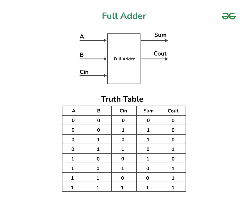
In Digital Logic Circuit, Full Adder is a Digital Logic Circuit that can add three inputs and give two outputs. The three inputs such as A, B, and input carry as Cin. The output carry is represented as Cout and the normal output is represented as S, Sum. The Cout is also known as the majority 1’s detector, whose output goes high when more than one input is high.
In Digital Logic Circuits, Full Adders are implemented using digital logic gates such as OR gate, AND gate, NOT gate, NAND gates, NOR gates, etc. In this article, we will explore Full Adders, and NAND Gates and execute the ImplementationofFull Adder using NAND Gates.
**What is a Full Adder?
Full Adder is a Digital Logic Circuits that can add three inputs and give two outputs i.e. three inputs such as A, B, and input carry as Cin and gives a sum output and carry output i.e. two outputs. A Full Adder Circuit performs as the brain of the most of Digital Logic Circuits that execute addition or subtraction.
A Full Adder require the use of nine NAND gates. The Arithmetic Logic Unit, ALU uses Full Adders. In a computer, Full Adders are utilized by the ALU to produce memory addresses and relocate the Program Counter to the next instruction.
Now, Here we will understand Full Adder by Block Diagram of Full Adder where we will discuss and explain it by using :
- Truth Table of Full Adder
- Logical Expression for Full Adder
Block Diagram of Full Adder
The Block Diagram of Full Adder is shown below
**Logical Expression of a Full Adder
Given below is the Expression for Full Adder which includes Sum and Carry
Sum=A ⊕ B ⊕ Cin
Cout= AB + ACin + BCin
Where, A, B, Cin are the Inputs of the Full Adder
**Applications of Full Adder
- **Arithmetic Circuits: Full adders are used in arithmetic circuits to add two double fold numbers. When unique Full Adders are connected in a chain, they can compute multi-bit paired numbers.
- **Data Handling: Full adders are used in information handling applications such as advanced signal manipulation, encoding of information, and mistake correction.
- **Counters: Full adders are used in counters to perform addition or decrement the count by one.
- **Multiplexers and Demultiplexers: Full adders are used in multiplexers and demultiplexers to choose and course information.
- **Addressing Memory: Full adders are used in memory addressing circuits to produce the location of a particular memory area.
- **ALUs: Full adders are used as a basic part of Number juggling Rationale Units (ALUs) used in chip and computerized signal processors.
What is a NAND Gate?
A NAND gate is one of the type of Universal Gates in which the two basic logic gates are combined as the NAND gate can implement any Boolean function without the use of basic gates and also find the results of logical inputs without the use of any other logic gates.
The NAND gate or “Not AND” gate is the combination of two basic logic gates are connected in series i.e. the AND gate and the NOT gate. NAND gate output is high when one of the two inputs is high or if both inputs are low. It means the output is always high and when both the inputs are high then the output is low.
Symbol of a NAND Gate
Given Below is the Symbol For NAND Gate
**Logical expression of a NAND Gate
In the expression, Two inputs are represented as A and B and the Output is X, then the expression is –
X = (A.B)’
.png)
NAND Gate
**Applications of NAND Gate
- **Universal Gate: NAND gate is known as Universal Gate because basic logic gates can be created using Universal Gate.
- **Data Store: NAND gates are utilized to establish sequential circuits such as Flip-Flops and Latches, which is a main part of data storage.
- **Arithmetic Logic: NAND gates are highly utilized in Arithmetic Logic Units (ALUs) of a computing device to execute operations such as addition, subtraction, etc.
- **Encoder and Decoder: NAND gates are utilized in Encoder and Decoder circuits to transform a binary code directly into a group of digital signals and vice versa.
- **Multiplexers and Demultiplexers: NAND gates are utilized in Multiplexers to conclude that a signal should take which path to arrive a single output. Demultiplexer is the reverse of Multiplexer.
- **Clock Generators: NAND gates utilized in Clock generators to execute clock signals where various operations are synchronized in Digital Circuit.
- **Logical Operations: NAND gates are also utilized to implement logical operations.
Implementation of Full Adder using NAND Gates
Implementation of Full Adder using NAND Gates is realization of Full Adder by using minimum nine NAND Gates during which we will have 2 outputs at the end namely Cout and Sum.
Given Below is the Circuit For Implementation of Full Adder using NAND Gates :

Full Adder Using NAND Gates
**Logical Expression for Full Adder using NAND Gate
Using Half Adder Equation of Sum, we get
Sum=A\overline{B}+\overline{A}B
=AA\overline{B}+\overline{A}B+A\overline{A}+B\overline{B} Because A\overline{A}=0
=A\overline{B}+A\overline{A}+\overline{A}B+B\overline{B} Because B\overline{B}=0
=A(\overline{B}+\overline{A})+B(\overline{A}+\overline{B})
=A(\overline{AB})+B(\overline{AB}) By De-Morgan's Theorem
=\overline{\overline{A(\overline{AB})+B(\overline{AB})}} Because \overline{\overline{A}}=A
Sum=\overline{\overline{A(\overline{AB})}.\overline{B(\overline{AB})}} By De-Morgan's Theorem
Using Half Adder Equation of Carry, we get
Carry=A.B
=\overline{\overline{A.B}} Because \overline{\overline{A}}=A
Sum=A\overline{B}+\overline{A}B
=\overline{\overline{A(\overline{AB})}.\overline{B(\overline{AB})}} Equation-1
For Full Adder Equation of Sum, we realize
Sum=A⊕B⊕Cin Put A⊕B=x
=x⊕Cin
=\overline{\overline{x(\overline{xCin})}.\overline{Cin(\overline{xCin})}} Comparing x⊕Cin with A⊕B, Using Equation 1, we get
Sum={(\overline{A\overline{B}+\overline{A}B).(\overline{(A\overline{B}+\overline{A}B).Cin)}.\overline{Cin(\overline{(A\overline{B}+\overline{A}B).Cin)}}}
Carry=AB+(A\overline{B}+\overline{A}B).Cin
=\overline{\overline{AB+(A\overline{B}+\overline{A}B).Cin}}
=\overline{\overline{AB}.\overline{((A\overline{B}+\overline{A}B).Cin)}}
Steps To Implement the Full Adder using NAND Gate
- To realize Full Adder Using NAND Gate, We apply Inputs as A and B to Gate 1 then Output of **Gate 1 is \overline{A.B}.
- Output of Gate 1 is given as input to Gate 2 and we give another input as A to Gate 2 then Output of Gate 2 is AB+\overline{A}.
- Output of Gate 1 is also given as input to Gate 3 and we give another input as B to Gate 3 then Output of Gate 3 is AB+\overline{B}.
- Output of Gate 2 is given as input to Gate 4 and Output of Gate 3 is given as another input to Gate 4 then Output of Gate 4 is A\overline{B}+\overline{A}B.
- Output of Gate 4 is given as input to Gate 5 and we give another input as Cin to Gate 5 then Output of Gate 5 is (\overline{A\overline{B}+\overline{A}B).Cin}.
- Output of Gate 5 is given as input to Gate 6 and Output of Gate 4 is given as another input to Gate 6 then Output of **Gate 6 is \overline{(A\overline{B}+\overline{A}B).((\overline{A\overline{B}+\overline{A}B).Cin})}.
- Output of Gate 5 is also given as input to Gate 7 and we give another input as Cin to Gate 7 then Output of Gate 7 is \overline{Cin.((\overline{A\overline{B}+\overline{A}B).Cin})}.
- Output of Gate 6 is given as input to Gate 8 and Output of Gate 7 is given as another input to Gate 8 then Output of **Gate 8 is \overline{\overline{(A\overline{B}+\overline{A}B).((\overline{A\overline{B}+\overline{A}B).Cin})}.\overline{Cin.((\overline{A\overline{B}+\overline{A}B).Cin})}}.
- So, we can see that output of Gate 8 is Sum, S i.e. A⊕B⊕Cin
- Output of Gate 5 is given as input to Gate 9 and Output of Gate 1 is given as another input to Gate 9 then Output of **Gate 9 is \overline{\overline{AB}.((\overline{A\overline{B}+\overline{A}B).Cin})}.
- Also, we can realize that output of Gate 9 is Carry, Cout i.e. AB+(A⊕B).Cin
Applications of Implementation of a Full Adder using NAND Gates
Given Below are the Applications of Implementation of a Full Adder using NAND Gates
- **Digital Calculators: Full adders are utilized in digital calculators to execute an arithmetic addition of two binary numbers. As an implementation of a Full Adder using NAND gates decreases the required number of gates , so that clarifies the design and decreases the overall circuit size.
- **Microprocessors: Full adders are utilized in microprocessors to execute arithmetic addition of two binary numbers. As an implementation of a Full Adder using NAND gates decreases the propagation delay, which enlarges the microprocessor speed.
- **Digital Signal Processing: Full adders are utilized in digital signal processing applications such as audio and video processing. As an implementation of a Full Adder using NAND gates decreases the power consumption and enlarges the circuit performance.
- **Cryptography: In cryptography, Full adders are utilized as applications like encryption and decryption. As an implementation of Full Adder using NAND gates reduces the circuit complexity, which makes the implementation more efficient and secure.
- **Control Systems: In control systems, Full Adders are utilized to perform some arithmetic operations on binary signals. As an implementation of full adder using NAND gates decreases the required number of gates, so that simplify the design and decreases the overall size of the circuit. Ultimately, Implementation of Full Adder using NAND gates gives several advantages, for eg decreased complexity, minimized overall size of circuit, and simplified design, making it a great choice in many applications of digital circuit.