NAND Gate (original) (raw)
Last Updated : 23 Jul, 2025
NAND Gate is the special type of logic gate which is also known as the Universal Gate, because it can be used to implement other basic logic gates like AND, OR, and NOT. It performs NAND(NOT AND) operation between two or more binary inputs and gives output binary signal. This is a combination of AND gate and NOT gate. It gives the output low(0) only when all of its inputs are high(1). In simple words we can say that NAND gate is the opposite (inverted) of AND Gate.
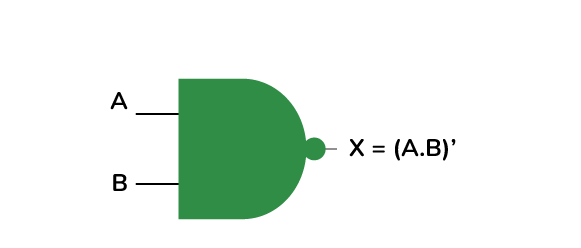
The Boolean expression for the NAND Gate is the complement of logical multiplication of inputs denoted by a full stop. Suppose we have two inputs, A and B and the output is called X, then the expression is
**X = (A . B)'
Operation of NAND GATE
NAND Gate takes Boolean values as input and returns
- Returns 1, if all the inputs are 0 or alternative (meaning one is 0, and the other is 1 or vice versa).
- Returns 0, if all inputs are 1
Types of NAND GATE
The NAND gate is classified into three types based on the number of inputs it takes.
2-Input NAND Gate
It is the simple form of NAND gate. In this type of NAND gate, there are only two input values and one output values. There are total of 22=4 combinations of inputs possible. The logic design and Truth table are mentioned below.

**3-Input NAND Gate
Unlike the 2 input NAND gate has two inputs, the 3-inputs NAND gate has total of three inputs. The NAND gate can be joined(cascaded) together to form individual inputs of any number. There are total of 23=8 combinations of inputs possible. The Boolean expression of NAND gate is defined as binary operation addition(+).

Multi Input NAND Gate
We can form NAND gate with any number of inputs i.e., n inputs. The output is low(0) only when all of its inputs are high(1). There are total of 2n combinations of inputs possible. When there is NAND gate with multiple inputs but you don't need to use all of them, then you can connect the unused inputs to the power supply i.e., set them high(1).However instead of connecting directly directly to the power, we can use pull-up resistors. These will helps to stabilize the input without drawing too much current, which helps to prevent changes in the circuit.
Multi Input NAND Gate
NAND Gate in Terms of Transistor
The NAND gate can be constructed using transistors, which are the key blocks of digital electronics. In this transistors acts as a small switches in a circuit, turning on or off based on the signal received from the input. In NAND gate, transistors is used to make sure that the output is low (0) only when all of its inputs are high (1). NAND gate can be implemented by using transistor in various configurations, but a common method is using two NPN transistors connected in series.

Working of NAND Gate in Terms of Transistor
In a transistor-based NAND gate, two or more NPN transistors are connected in series (one after the other). The key concept here is that for the output to be low (0), all the transistors must be on. This means that each input must provide the required signal to turn on its corresponding transistor.
- The positive voltage supply (Vcc) is connected to a pull-up resistor, which is then connected to the output.
- The collector of the first transistor (T1) is connected to the pull-up resistor and the positive supply (Vcc), while the emitter of T1 is connected to the collector of the second transistor (T2).
- The emitter of T2 is connected to ground (0V).
- The inputs, A and B, are connected to the bases of T1 and T2, respectively.
- **Both Inputs Low (A = 0, B = 0): When both inputs are low (0), neither transistor turns on, so no current flows from the output to ground. The pull-up resistor keeps the output at a high (1) state. This results in a high output.
- **One Input High (A = 1 or B = 1): When either input is high (1), the corresponding transistor turns on. However, since the transistors are in series, current cannot flow all the way to ground unless both transistors are on. The output remains high (1).
- **Both Inputs High (A = 1, B = 1): When both inputs are high (1), both transistors turn on, completing the circuit path from Vcc to ground through the transistors. This pulls the output down to a low (0) state.
Applications of NAND Gate
- **Universal Gate: NAND gate is called Universal Gate because all the basic logic gates can be formed using them.
- **Arithmetic Logic: NAND gates are extensively used in the Arithmetic and Logic Units (ALUs) of a computing device to perform operations like addition, subtraction, etc.
- **Used in Decoder and Encoder: NAND gates are also used in Decoder and Encoder circuits to convert a binary code into a set of digital signals and vice versa.
- **Used in Multiplexers and Demultiplexers: NAND gates are used in Multiplexers to decide which route a signal should take to reach a single output. The demultiplexer does the exact opposite of this.
- **Logical Operations: NAND gates are also used to implement various logical operations.
Advantages of NAND Gate
- **It is a Universal Gate: NAND gate is a Universal Gate, so it can be used to construct any basic logic gate without using any other Gate. Also, it can solve complex Logical Problems.
- **Simplify Logical Expressions: Using only the NAND gate, we can simplify any complex logical circuits and represent them in a simpler manner.
- **Low Components Needed: NAND gate can represent any other logic gate, we can utilize NAND gates to solve complex logical expressions, and as a result, a small number of NAND gates are required.
- **Less Power Consumption: Implementing logical functions using a NAND gate consumes way less power than other gates.
Disadvantages of NAND Gate
- **Lack of Flexibility: Although NAND is a Universal Gate, implementing all logic circuits using a NAND gate might not always yield the most optimized result.
- **Speed: In some cases using the NAND gate might result in a propagation delay, those logical expressions might need some dedicated Gates to resolve.