OR Gate (original) (raw)
Last Updated : 22 Nov, 2025
OR GATE is most widely used digital logic circuit and is known as a primitive digital electronics building block in digital logic. The output state of OR gate will be high i.e.,(1) if any of the input state is high or 1, else output state will be low i.e., 0.
The Boolean Expression for the OR gate is the logical addition of inputs denoted by plus sign(+) as
X= A+B
The value of X will be high(true) when one of the inputs is set to high (true).
Inputs and Outputs in OR Gate
- **Input: The input of an OR gate is the binary signal provided by the user to its input terminals on which it will perform logical operations and provide output.
- **Output: The output of an OR gate is the result that came after a logical operation performed on its inputs. It can be high means (1) or low (0). A single output is provided after an operation.
There are some simple OR gates that take only one input but there are also OR gates that take more than one input they are known as Multi-Input OR Gate.
Types of Logic OR Gate
There are basically three types of OR GATE
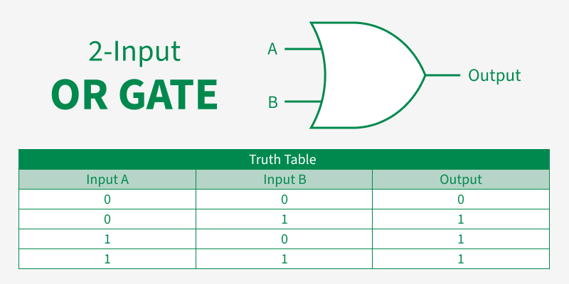
**2-Input Logic OR GATE
This is the simplest form of OR Gate. In this It takes only two inputs and provides single output. It gives a high output (1) if at least one of the binary inputs is high (1). There are total of 22 =4 combinations of inputs.
**X= (A+B)
The Logic design and Truth Table of the OR gate are given below.
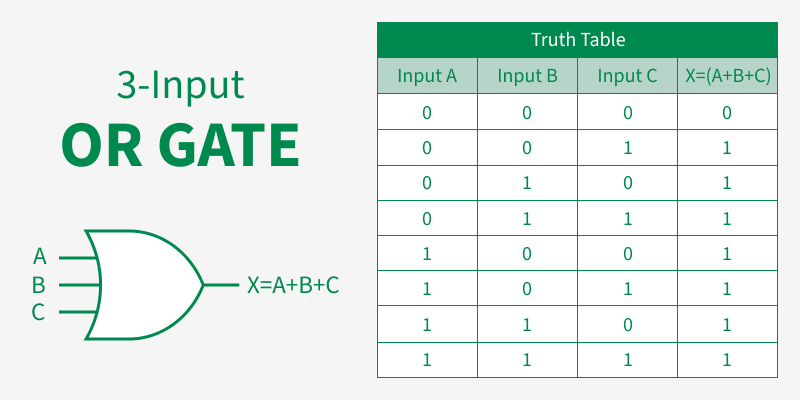
3- Input Logic OR Gate
The OR Gate can also have any number of individual input. Multiple OR gate can be connected together to handle more inputs. It can take more than two inputs. Its working is as same as2 input OR gate i.e. takes multiple inputs and provides high output if at least one input is high (1). For three input OR Gate there are total of 23=8 possible combinations of inputs.
**X=(A+B+C)
The Logic design and truth table are shown below
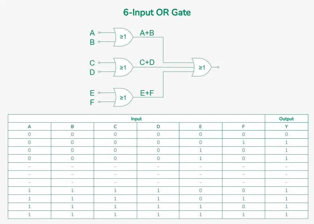
Multi Input Logic OR Gate
A Multi Input OR Gate is simply an OR gate that has multiple inputs. The n-input OR Gate can also be formed. If there are n inputs, then (N/2)+1 OR gates will be used.
**For Example:
If we have 6 input A, B, C, D, E, F, then 4 OR Gates are used in the logic design of 6-Input OR Gate. There is the following Representation of 6 input OR Gate.
Y=(A+B)+(C+D)+(E+F)
In simple words, it is expressed as:
Y= A OR B C OR D E OR F
**OR Gate Circuit Diagram Using Transistors
An OR gate can be made using transistors, typically with **NPN transistors in a basic configuration. The basic idea of this combination is to control the output using two inputs, where either input can turn on a transistor, resulting in a high output (1).
Below is the simple construction of a simple OR gate circuit using transistors to demonstrate the required components and the circuit's functioning.

**Components Needed for Construction of OR Gate
- Resistance
- NPN transistor
- power supply in voltage
- wires
- switches
**Working of the Circuit
- When both switches (inputs A and B) are in the OFF state (LOW), there is no power supply to the bases of the transistors.
- As a result, both the base-to-emitter and base-to-collector junctions of the transistors have a voltage lower than the threshold voltage of a diode.
- This causes both transistors to go into their cutoff state, acting like open switches and blocking current flow.
- With no current flowing through the transistors, the output remains in a low voltage state (LOW), turning off the LED connected to the output.
Applications of OR Gate
- **Automatic Watering System: OR gate can be used to create a simple watering system. If any of the sensors demand water (high) then the output will become high means the watering system will turn on.
- **Home Automation: OR gates can be part of home automation systems. They can be used to combine signals from various sensors and switches to trigger specific actions, such as turning on the heating or cooling system when any room temperature exceeds or declines a specific number.
- **Emergency Lighting: In the event of a power outage, OR gates can be used to combine signals from multiple emergency switches if any of the switches is high means turned on then emergency lighting will turn on.
**Advantages of OR Gate
- **Simplicity: OR gates are simple and easy-to-use logic gates. Their design is also simple and understandable.
- **Flexibility: OR gate works with also works with multiple inputs which increases their applications and digital use so it's very flexible to use.
- **High Importance: OR gates are said to be fundamental building blocks in digital electronics. They act as a base for complex IC(integrated circuits). Without OR Gate making circuits is not possible.
- **Implementation of Logical Functions: Creating Functionality of other logic gates such as NAND, NOR, and XOR gates, is possible using OR gate.
**Disadvantages of OR Gate
- **Loss of Information: By OR Gate functionality we can only understand that one of the provided many inputs is high but we cannot know which of the input is high so it doesn't provide complete information.
- **Lack of Precision: In certain applications that require precise decision-making based on individual input values, the OR gate might not be suitable as it only produces a binary output (1 or 0).
- **Non-Invertible: The OR gate is not invertible; its output is always high (1) when at least one input is high (1). It cannot produce a low output (0) for any specific input combination.
- **Increased Power Consumption: Since the OR gate requires more transistors compared to other basic gates like NOT and AND gates, it can consume more power in complex circuits.