Universal Logic Gates (original) (raw)
Last Updated : 23 Jul, 2025
A logic gate is an active electronic component that uses one or more inputs to produce an output based on the bolean algebra each gate is designed to perform. Though there are various types of gates including AND, OR, NOT, NAND, NOR etc.. NAND and NOR gates are a little special. NAND gate and NOR gate can be termed as universal logic gates since any arbitrary Boolean function can be implemented using NAND gate or NOR gate alone. This makes NAND and NOR universal gates for developing every other digital logic gates in the technological world.
In this particular article, we have a given a detailed description of universal logic gates. We will understand the way in which other all logical gates such as NOT, AND, OR, XOR, and XNOR gates can be implemented using NAND or NOR gates alone.
Table of Content
- What are Universal Gates?
- NAND Gate
- NOR Gate
- Realizing Basic Gates Using NAND and NOR
- Applications of Universal Logic Gates
What are Universal Gates?
The universal gates are the logic gates that are versatile in that they can be programmed to execute any Boolean function. The most popular types among them are NAND and NOR gates.
To explain it further, the input of the universal gates can be interconnected in one way or the other while the inputs can also be inverted in one way or the other to get the AND, OR, NOT, XOR and XNOR basic Boolean functions.
They are very versatile to be core components when it comes to the implementation of digital circuits and processors. By employing just a single gate or by combining both these gate types, it is possible to construct intricate logic systems.
NAND Gate
A NAND gate is a combination of an AND gate followed by a NOT gate. It outputs a 0 only when all its inputs are 1; otherwise, it outputs 1.
**Symbol and Truth Table

NAND Gate
NOR Gate
A NOR gate is a combination of an OR gate followed by a NOT gate. It outputs a 1 only when all its inputs are 0; otherwise, it outputs 0.
**Symbol and Truth Table
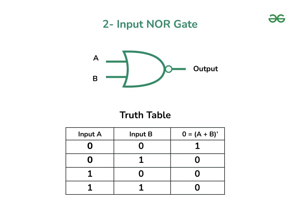
NOR Gate
Realizing Basic Gates Using NAND and NOR
Implementing Basic Gates using NAND Gate
We will see Implementing Basic Gates using NAND Gate :
**NOT Gate (Inverter)
**Circuit: Connect both inputs of a NAND gate to the same input signal.
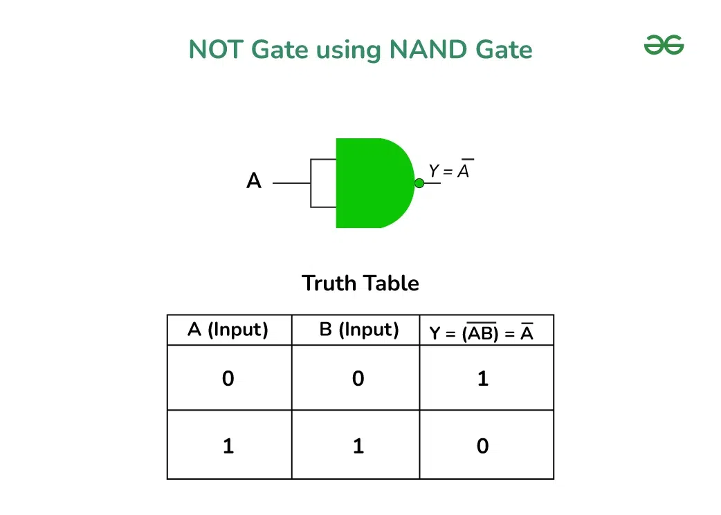
NOT GATE USING NAND GATE
**Circuit: Connect the outputs of two NAND gates to the inputs of a third NAND gate.
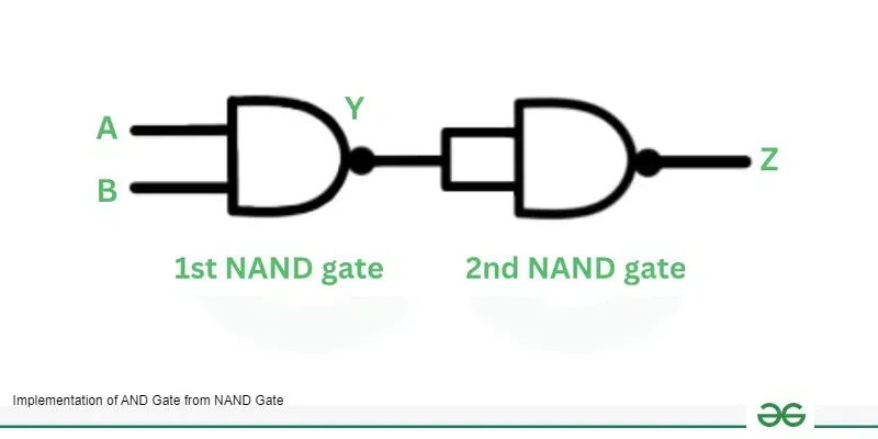
AND Gate using NAND Gate
**Truth Table
| A | B | Z |
|---|---|---|
| 0 | 0 | 0 |
| 0 | 1 | 0 |
| 1 | 0 | 0 |
| 1 | 1 | 1 |
**Circuit: Connect each input to a NAND gate and then connect the outputs of these gates to the inputs of another NAND gate.

OR Gate BY USING NAND GATE
**Truth Table
| A | B | Output (A OR B) |
|---|---|---|
| 0 | 0 | 0 |
| 1 | 0 | 1 |
| 0 | 1 | 1 |
| 1 | 1 | 1 |
**Circuit: Connect the outputs of two NAND gates to the inputs of a third NAND gate. Then, feed the output of this gate into another NAND gate configured as a NOT gate.
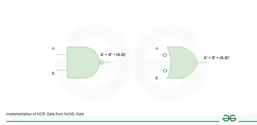
NOR GATE USING NAND GATE
**Truth Table
| A | B | A NOR B |
|---|---|---|
| 0 | 0 | 1 |
| 0 | 1 | 0 |
| 1 | 0 | 0 |
| 1 | 1 | 0 |
**Circuit: Utilize a combination of four NAND gates.
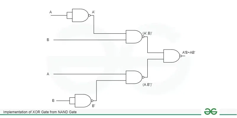
XOR Gate USING NAND GATE
**Truth Table
| A | B | A XOR B |
|---|---|---|
| 0 | 0 | 0 |
| 0 | 1 | 1 |
| 1 | 0 | 1 |
| 1 | 1 | 0 |
**Circuit: Connect the output of an XOR gate to a NAND gate configured as a NOT gate.

XNOR Gate USING NAND GATE
**Truth Table
| A | N | A XNOR B |
|---|---|---|
| 0 | 0 | 1 |
| 0 | 1 | 0 |
| 1 | 0 | 0 |
| 1 | 1 | 1 |
Implementing Basic Gates using NOR Gate
We will see Implementing Basic Gates using NOR Gate :
**NOT Gate (Inverter)
**Circuit: Connect both inputs of a NOR gate to the same input signal.
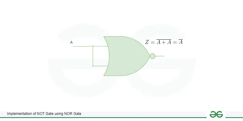
NOT Gate using NOR Gate
**Truth Table
| A | Output (NOT A) |
|---|---|
| 0 | 1 |
| 1 | 0 |
**AND Gate
**Circuit: Use three NOR gates. First, connect each input to a NOR gate and then connect their outputs to the inputs of another NOR gate.
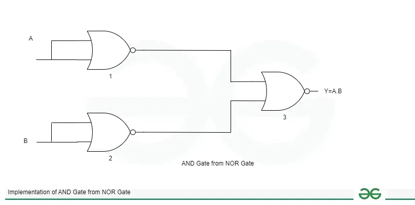
AND Gate USING NOR GATE
**Truth Table
| A | B | Output (A AND B) |
|---|---|---|
| 0 | 0 | 0 |
| 0 | 1 | 0 |
| 1 | 0 | 0 |
| 1 | 1 | 1 |
**OR Gate
**Circuit: Use a combination of NOR gates, with the final gate configured as a NOT gate.
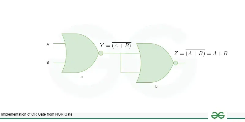
OR Gate USING NOR GATE
**Truth Table
| A | B | Y Output (A OR B) |
|---|---|---|
| 0 | 0 | 0 |
| 0 | 1 | 1 |
| 1 | 0 | 1 |
| 1 | 1 | 1 |
**NAND Gate
**Circuit: Use a combination of three NOR gates.
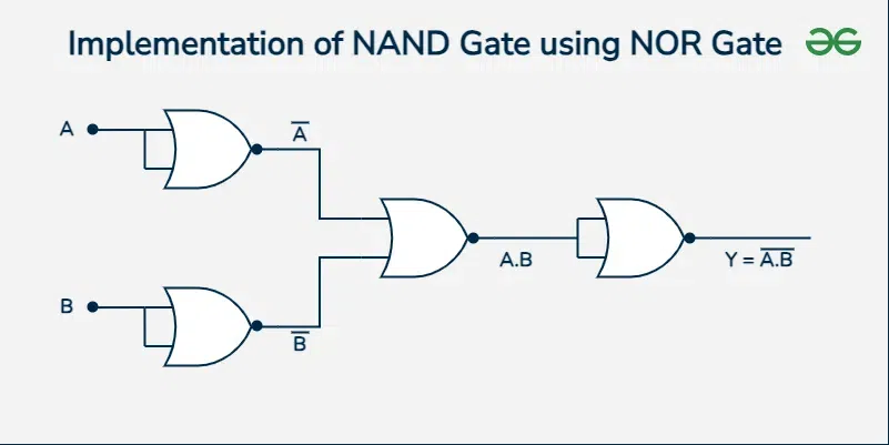
Implementation of NAND gate using NOR gate
**Truth Table
| A | B | OUTPUT(A NAND B) |
|---|---|---|
| 0 | 0 | 1 |
| 0 | 1 | 1 |
| 1 | 0 | 1 |
| 1 | 1 | 0 |
**XOR Gate
**Circuit: Utilize a combination of five NOR gates.
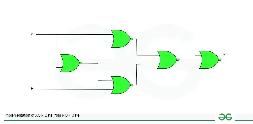
XOR Gate using NOR GATE
**Truth Table
| A | B | OUTPUT(A XOR B) |
|---|---|---|
| 0 | 0 | 0 |
| 0 | 1 | 1 |
| 1 | 0 | 1 |
| 1 | 1 | 0 |
**XNOR Gate
**Circuit: Connect the output of an XOR gate (realized using NOR gates) to another NOR gate configured as a NOT gate.

Implementation of XNOR Gate using NOR GATE
**Truth Table
| A | B | OUTPUT(A X NOR B) |
|---|---|---|
| 0 | 0 | 1 |
| 0 | 1 | 0 |
| 1 | 0 | 0 |
| 1 | 1 | 1 |
Applications of Universal Logic Gates
- **Computer processors: NAND or NOR gates serves as the basic building block for microprocessors and other ICs incorporating complex functionalities.
- **Simple logic circuits: Universal gates enable any Boolean function to be computed using the gate of a single type in the circuitry design.
- **Programmable logic devices (PLDs): FPGAs for instance, incorporate logic functions based on look-up tables which are constructed from for NAND or NOR gates defined by the customer.
- **Minimalist circuit design: It becomes possible for engineers to develop circuits containing the fewest components as they can design circuits with the help of only NAND or NOR gates.
- Universal gates can be wired together to form standard digital subcircuits such as arithmetic circuits like adder circuits, circuits for decoding and encoding, multiplexer and demultiplexer circuits etc.
- The controllability of inputs and scalability of outputs enable the subsequent logic for addition, flip flops, and memory etc.
Conclusion
From this article we can ungerstand why NAND and NOR gates are considered to be unique in the realm of digital logic design, as they are reversible. From the above simple implementation of the universal gate, it was clear that all the gates such as NOT, AND, OR, XOR AND XNOR and any other boolean logic function can be implemented. To be able to perform all of the basic logical operations with just one gate type also makes integrated circuit fabrication easier and requires fewer parts.