Usage of Different Subsystem Types - MATLAB & Simulink (original) (raw)
To learn how to use different types of subsystems in your design and model your algorithm hierarchically, use these guidelines. Each guideline has a severity level that indicates the level of compliance requirements. For more information, see HDL Modeling Guidelines Severity Levels.
Virtual Subsystem: Use as DUT
Guideline ID
2.4.1
Severity
Strongly Recommended
Description
A virtual subsystem is a subsystem that is not a conditionally-executed subsystem or an Atomic Subsystem. By default, a regular Subsystem block that you add to your Simulink® model is a virtual subsystem. Non-virtual subsystem types includeAtomic Subsystem, model reference, Variant Subsystem, and a variant model.
To determine whether a subsystem is virtual, use the get_param function with the parameter IsSubsystemVirtual. For example:
get_param('sfir_fixed/symmetric_fir', 'IsSubsystemVirtual')
Atomic and Virtual Subsystems: Generate Reusable HDL Files
Guideline ID
2.4.2
Severity
Recommended
Description
To generate a single HDL file for identical instances of the subsystems that you use at lower levels of a hierarchy, see Generate Reusable Code for Subsystems and Code reuse.
To enable resource sharing on a subsystem unit, see General Considerations for Sharing of Subsystems.
You must turn off signal logging for generating reusable code from atomic and virtual subsystems. Generation of reusable code from atomic and virtual subsystem might not succeed if you log the signals inside the subsystems.
Variant Subsystem: Using Variant Subsystems for HDL Code Generation
Guideline ID
2.4.3
Severity
Mandatory
Description
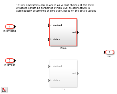
The Variant Subsystem block is a template preconfigured to contain two Subsystem blocks to use as Variant Subsystem choices. During simulation, a variant control decides which of the two Subsystem blocks is active. Therefore, you can use the Variant Subsystem to create two different configurations or subsystem behaviors and then specify the active configuration at the model compile stage or simulation-loop stage of simulation. For more information on the Variant Subsystem block, see Variant Subsystem.
- You cannot use a Variant Subsystem as the DUT. To generate code, place the Variant Subsystem inside the Subsystem that you want to use as the DUT. The file name and instance name of the generated code is created only for the active configuration or both active and inactive configurations.
- You cannot share multiple Variant Subsystem blocks by using the Variant Subsystem optimization.
- You must make sure that when verifying the functionality of the generated code, the active variant that you used when simulating the model is the same as the active variant that you used for generating HDL code.
For an example, open the model hdlcoder_variant_subsystem_design.slx. If you open the DUT Subsystem, you see a Variant Subsystem block, Divide. The Variant Subsystem has two different subsystems, Recip and Op. If you open the Block Parameters dialog box for the Divide Subsystem, you see the Variant control expression and the Condition that determines which Subsystem to enable during simulation. The Variant activation time determines at which stage of simulation to enable the Subsystem. In this case, Rcp is 1 and the activation time is update diagram. The Recip Subsystem becomes active during simulation.
load_system('hdlcoder_variant_subsystem_design') set_param('hdlcoder_variant_subsystem_design','SimulationCommand','Update') open_system('hdlcoder_variant_subsystem_design/DUT/Divide')
Generated Code
To generate HDL code, run this command:
makehdl('hdlcoder_variant_subsystem_design/DUT');
An HDL file with the name Recip.vhd is generated because the Recip Subsystem is active at code generation time and therefore has code generated for it.
To generate HDL code for both Recip and Op, change the settings of these parameters on the Block Parameters dialog box of the Divide Subsystem, then run the makehdl command.
1. Set Variant activation time to startup.
set_param('hdlcoder_variant_subsystem_design/DUT/Divide','VariantActivationTime','startup')
2. Set the variant control variable Rcp of type Simulink.VariantControl, normal MATLAB® variable, or Simulink.Parameter and set its value to an integer value. In this example, Rcp is a normal MATLAB variable with an int16 value.
3. Set Built-in empty choice to on.
set_param('hdlcoder_variant_subsystem_design/DUT/Divide','EmptyChoice','on')
4. Set Propagate conditions outside of variant subsystem to off.
set_param('hdlcoder_variant_subsystem_design/DUT/Divide','PropagateVariantConditions','off')
Note: Ensure that Treat as atomic unit of Recip and Op Subsystems is set to on.
set_param('hdlcoder_variant_subsystem_design/DUT/Divide/Recip','TreatAsAtomicUnit','on') set_param('hdlcoder_variant_subsystem_design/DUT/Divide/Op','TreatAsAtomicUnit','on')
Generate the HDL code using the following command.
makehdl('hdlcoder_variant_subsystem_design/DUT');
HDL files with the name Recip.vhd and Op.vhd are generated because the code is generated for both the Recip and Op Subsystems.
HDL Coder generates the following VHDL® code for the Variant Subsystem Divide, which has its variant control variable set to a tunable parameter, Rcp. The code generator creates a DUT port and adds a comment to indicate that the port corresponds to a tunable parameter. You can change the value of Rcp by providing the value to the pin on the chip that is mapped to Rcp.
ENTITY Divide IS PORT( clk : IN std_logic; reset : IN std_logic; enb : IN std_logic; in_dividend : IN std_logic_vector(15 DOWNTO 0); -- sfix16_En14 in_divisor : IN std_logic_vector(15 DOWNTO 0); -- sfix16_En13 Rcp : IN std_logic_vector(23 DOWNTO 0); -- sfix24_En9 Tunable port out_rsvd : OUT std_logic_vector(23 DOWNTO 0) -- sfix24_En9 ); END Divide;
VariantMerge_For_Outport_out_out1 <= Op_out1_signed WHEN Selected_Index_floor = to_signed(16#0001#, 15) ELSE Recip_out1_signed WHEN Selected_Index_floor = to_signed(16#0002#, 15) ELSE GroundForVM_out_out1;
Model References: Build Model Design Using Smaller Partitions
Guideline ID
2.4.4
Severity
Recommended
Description
Modeling a large design hierarchically can increase code generation time. If you specify generation of reports such as the traceability report, the code generation time can further increase significantly. To avoid such performance issues, it is recommended that you partition your design into smaller partitions. Use the Model block to unify a model that consists of smaller partitions. It also enables incremental code generation. You can generate HDL code for the parent model or the referenced model. To see the generated HDL code, in the hdlsrc folder, a folder is created for the parent model with a separate subfolder for the referenced model.
When generating the HDL test bench, if the test bench consists of blocks that operate with a continuous sample time, you can convert the DUT to a referenced model. This conversion enables the DUT to run at a fixed-step, discrete sample time. To learn more, see Convert DUT Subsystem to Model Reference for Testbenches with Continuous Blocks.
For an example, open the model hdlcoder_divide_parentmodel.slx. When you double-click the DUT Subsystem, you see a Model block that references the model hdlcoder_divide_referencedmodel.
load_system('hdlcoder_divide_parentmodel') set_param('hdlcoder_divide_parentmodel', 'SimulationCommand', 'Update') open_system('hdlcoder_divide_parentmodel/DUT')
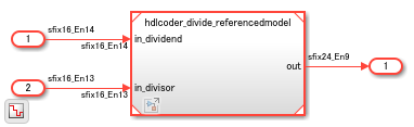
To see the referenced model, double-click the Model block:
open_system('hdlcoder_divide_parentmodel/DUT/Model')
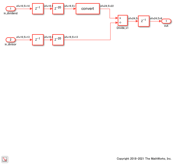
To generate HDL code, enter this command:
makehdl('hdlcoder_divide_parentmodel/DUT')
For more information, see Model Referencing for HDL Code Generation.
Block Settings of Enabled and Triggered Subsystems
Guideline ID
2.4.5
Severity
Mandatory
Description
A Triggered Subsystem is a subsystem that receives a control signal via a Trigger block. The Triggered Subsystem executes for one cycle each time a trigger event occurs. When you generate HDL code for a triggered subsystem:
- Do not use the Triggered Subsystem block as the DUT. Place the Triggered Subsystem inside anotherSubsystem block, and use thatSubsystem as the DUT.
- You can add unit delays to the output signals of theTriggered Subsystem, outside of theTriggered Subsystem block. The unit delays prevents HDL Coder™ from inserting additional bypass registers in the HDL code.
- Make sure that the Use trigger signal as clock setting does not result in timing mismatches when you simulate the testbench to verify the generated code. To learn more, see Using Triggered Subsystems for HDL Code Generation.
For other preferences when configuring the Triggered Subsystem block for HDL code generation, see HDL Code Generation on theTriggered Subsystem page.
An Enabled Subsystem is a subsystem that receives a control signal via an Enable block. The Enabled Subsystem executes at each simulation step where the control signal has a positive value. When you generate HDL code for an Enabled Subsystem:
- Do not use the Enabled Subsystem block as the DUT. Place the Enabled Subsystem inside anotherSubsystem block, and use thatSubsystem as the DUT.
- You can add a State Control block in
Synchronousmode inside the Enabled Subsystem to generate more efficient and hardware-friendly HDL code. The State Control block inSynchronousmode prevents HDL Coder from inserting additional bypass registers in the HDL code. The State Control block converts theEnabled Subsystem block to an Enabled Synchronous Subsystem block. To learn more, see Synchronous Subsystem Behavior with the State Control Block. - If you want a State Control block in
Classicmode or do not want a to add aState Control block, you can add unit delays to the output signals of the Enabled Subsystem, outside of the Enabled Subsystem block, to prevent HDL Coder from inserting additional bypass registers in the HDL code.
For other preferences when configuring the Enabled Subsystem block for HDL code generation, see HDL Code Generation on theEnabled Subsystem page.