interferometers (original) (raw)
Definition: optical devices utilizing the phenomenon of interference
Categories:  photonic devices,
  optical metrology
- interferometers
- etalons
- common-path interferometers
- Fabry–Perot interferometers
- Fizeau interferometers
- Gires–Tournois interferometers
- Mach–Zehnder interferometers
- Michelson interferometers
- Twyman–Green interferometers
- white light interferometers
- (more topics)
Related: interferenceoptical phasespectral phase interferometryMichelson interferometersTwyman–Green interferometersGires–Tournois interferometersFabry–Pérot interferometersFizeau interferometerswhite light interferometersoptical metrologydistance measurements with lasersoptical heterodyne detection
Page views in 12 months: 6459
DOI: 10.61835/kva Cite the article: BibTex BibLaTex plain textHTML Link to this page! LinkedIn
Content quality and neutrality are maintained according to our editorial policy.
📦 For purchasing interferometers, use the RP Photonics Buyer's Guide — an expert-curated directory for finding all relevant suppliers, which also offers advanced purchasing assistance.
Contents
What are Interferometers?
An interferometer is an optical device which utilizes the effect of interference. That can be done with different kinds of radiation, but this article specifically deals with optical interferometers, i.e., interferometer for light. Typically, such a device is based on the following operation principle: it starts with some input beam, splits it into two separate beams with some kind of beam splitter (a partially transmissive mirror), possibly exposes some of these beams to some external influences (e.g. some length changes or refractive index changes in a transparent medium), and recombines the beams on another beam splitter. The power or the spatial shape of the resulting beam can then be used e.g. for a measurement.
Interferometers frequently need to be made from high-quality optical elements. For example, one often uses mirrors and optical flats with a high degree of surface flatness.
Types of Interferometers
Mach–Zehnder Interferometer

Figure 1: Mach–Zehnder interferometer.
The Mach–Zehnder interferometer was developed by the physicists Ludwig Mach and Ludwig Zehnder. As shown in Figure 1, it uses two separate beam splitters (BS) to split and recombine the beams, and has two outputs, which can e.g. be sent to photodetectors. The optical path lengths in the two arms may be nearly identical (as in the figure), or may be different (e.g. with an extra delay line). The distribution of optical powers at the two outputs depends on the precise difference in optical arm lengths and on the wavelength (or optical frequency).
If the interferometer is well aligned, the path length difference can be adjusted (e.g. by slightly moving one of the mirrors) so that for a particular optical frequency the total power goes into one of the outputs. For misaligned beams (e.g. with one mirror being slightly tilted), there will be some fringe patterns in both outputs, and variations of the path length difference affect mainly the shapes of these interference patterns, whereas the distribution of total powers on the outputs may not change very much.
Michelson Interferometer

Figure 2: Michelson interferometers.
A Michelson interferometer, as invented by Albert Abraham Michelson, uses a single beam splitter for separating and recombining the beams. If the two mirrors are aligned for exact perpendicular incidence (see the upper figure), only one output is accessible, and the light of the other output goes back to the light source. If that optical feedback is unwanted (as is often the case with a laser, which might be destabilized), and/or access to the second output is required, the recombination of beams can occur at a somewhat different location on the beam splitter. One possibility is to use retroreflectors, as shown in the lower figure; this also has the advantage that the interferometer is fairly insensitive to slight misalignment of the retroreflectors. Alternatively, simple mirrors at slightly non-normal incidence can be used.
If the path length difference is non-zero, as shown in both parts of the figure, constructive or destructive interference e.g. for the downward-directed output can be achieved only within a finite optical bandwidth. Michelson originally used a broadband light source in the famous Michelson–Morley experiment, so that he had to build an interferometer with close to zero arm length difference.
There are many variations of the Michelson interferometer. For example, a Twyman–Green interferometer is essentially a Michelson interferometer with expanded beams in its arms. It is used for characterizing optical elements.
For more details, see the articles on Michelson interferometers and Twyman–Green interferometers.
Fabry–Pérot Interferometer

Figure 3: Fabry–Pérot interferometer.
A Fabry–Pérot interferometer (Figure 3) consists of two parallel mirrors, allowing for multiple round trips of light. (A monolithic version of this can be a glass plate with reflective coatings on both sides.) For high mirror reflectance, such a device can have very sharp resonances (a high finesse), i.e. exhibit a high transmittance only for optical frequencies which closely match certain values. Based on these sharp features, distances (or changes in distances) can be measured with a resolution far better than the wavelength. Similarly, resonance frequencies can be defined very precisely.
A modified version is the Fizeau interferometer, which is used for characterizing optical surfaces.
Another special kind of Fabry–Pérot interferometer, used for dispersion compensation, is the Gires–Tournois interferometer.
For more details, see the articles on Fabry–Pérot interferometers.
Sagnac Interferometer

Figure 4: Sagnac interferometer.
A Sagnac interferometer (named after the French physicist Georges Sagnac) uses counterpropagating beams in a ring path, realized e.g. with multiple mirrors (as in Figure 4) or with an optical fiber. If the whole interferometer is rotated e.g. around an axis which is perpendicular to the drawing plane, this introduces a relative phase shift of the counterpropagating beams (Sagnac effect). The sensitivity for rotations depends on the area covered by the ring, multiplied by the number of round trips (which can be large e.g. when using many turns in an optical fiber). It is possible e.g. to obtain a sensitivity which is sufficient for measuring the rotation of the Earth around its axis.
Sagnac interferometers are used e.g. in inertial guidance systems.
Common-path Interferometers
Common-path interferometers use a common beam path but e.g. different polarization states for the two beams. This has the advantage that fluctuations in the geometric path length do not affect the interferometer output, whereas the interferometer can be a sensitive detector for birefringence. The Sagnac interferometer (see above) is another example; here, the interfering beams have opposite propagation directions.
Fiber Interferometers
All the interferometer types discussed above can also be implemented with optical fibers. Instead of beam splitters, one then uses fiber couplers.
A potential difficulty is that the polarization state of light may change during propagation in the fiber. This often requires one to include a fiber polarization controller (which may occasionally have to be readjusted) or to use polarization-maintaining fibers.
Also note that temperature changes in the fibers (as well as bending) can affect the optical phase shifts. This can be a problem if different fibers belong to different interferometer arms. However, there are also fiber interferometers where one fiber serves for both arms, e.g. using two different polarization directions in the same fiber.
Physical Principles of Interferometers
There are also substantially different principles of using interferometers. For example, Michelson interferometers are used in very different ways, using different types of light sources and photodetectors:
- When a light source with low optical bandwidth is used (perhaps even a single-frequency laser), the detector signal varies periodically when the difference in arm lengths is changed. Such a signal makes it possible to do measurements with a depth resolution well below the wavelength, but there is an ambiguity. For example, a monotonic increase or decrease of the arm length difference leads to the same variation of the detected signal. This problem may be solved by modulating the arm length difference e.g. with a vibrating mirror (or with an optical modulator) and by monitoring the resulting modulation on the detector in addition to the average signal power. Simultaneous operation of an interferometer with two wavelengths is another way of removing the ambiguity.
- If the detector is a kind of camera (e.g. a CCD chip) and the surfaces monitored are fairly smooth, the phase profile (and thus the profile of optical path length) can be reconstructed by recording several images with different overall phase shifts (phase-shifting interferometry). A phase-unwrapping algorithm can be used to retrieve unambiguously surface maps extending over more than a wavelength. However, such methods may not work for rough surfaces or for surfaces with steep steps.
- A white light interferometer uses a broadband light source (e.g., a superluminescent diode), so that interference fringes are observed only in a narrow range around the point of zero arm length difference. In that way, the above-mentioned ambiguity is effectively removed.
- A wavelength-tunable laser can be used to record the detector signal for different optical frequencies. From such signals, the arm length difference can be unambiguously retrieved. This works also with two-dimensional detectors (e.g. CCD cameras).
- If one of the mirrors is intentionally tilted, an interference fringe pattern is obtained. Any change in arm length difference will then move the fringe pattern. This method makes it possible to measure phase changes sensitively and also to measure position-dependent phase changes, e.g. in some optical element.
- Instead of measuring distances, one can use interferometers for characterizing light. For example, the optical spectrum can be obtained by measuring the detector signal vs. arm length difference and applying a Fourier transform (Fourier transform spectroscopy). One can also retrieve wavelength-dependent phase shifts, for example for measuring chromatic dispersion of optical elements.
Another class of interferometric methods is named spectral phase interferometry. Here, interference in the spectral domain is exploited. The spectral modulation period is essentially determined by a time delay.
Applications
Interferometers can be used for many different purposes — by far not only for length measurements. Some examples are:
- for the measurement of a distance (or changes in a distance or a position, i.e., a displacement) with an accuracy of better than an optical wavelength (in extreme cases, e.g. for gravitational wave detection, with a sensitivity many orders of magnitude below the wavelength)
- for measuring the wavelength e.g. of a laser beam (→ wavemeter), or for measuring the full optical spectrum
- for monitoring slight changes in an optical wavelength or frequency (typically using the transmittance curve of a Fabry–Pérot interferometer) (frequency discriminators)
- for measuring rotations (with a Sagnac interferometer)
- for measuring slight deviations of an optical surface from perfect flatness (or from some other shape)
- for measuring the linewidth of a laser (→ self-heterodyne linewidth measurement, frequency discriminator)
- for revealing tiny refractive index variations or induced index changes in a transparent medium
- for modulating the power or phase of a laser beam, e.g. with a Mach–Zehnder modulator in an optical fiber communication system
- for measurements of the chromatic dispersion of optical components
- as an optical filter
- for the full characterization of ultrashort pulses via spectral phase interferometry
The first very prominent interferometer-based scientific experiment was the Michelson–Morley experiment in the context of the search for an ether wind. The most recent large discovery based on measurements with interferometers was the detection of gravitational waves [15]. Interferometers played vital roles also in many other scientific discoveries, e.g. in quantum optics.
Depending on the application, the demands on the light source in an interferometer can be very different. In many cases, a spectrally very pure source, e.g. a single-frequency laser is required. Sometimes, the laser has to be wavelength-tunable. In other cases (e.g. for dispersion measurements with white light interferometers), a light source with a very broad and smooth optical spectrum is required.
Noise Influences
Interferometric measurements can be subject to various types of noise:
- Mechanical noise (vibrations, shocks etc.) can affect measurements; one often needs to employ sophisticated mechanical means for suppressing such influences.
- There can be technical noise from light sources, e.g. laser noise, but also quantum noise influences. Typically, vacuum noise entering the open input port at a beamsplitter defines the standard quantum limit (shot noise limit) for the sensitivity [2, 5]. A noise level below that limit can sometimes be achieved by injecting squeezed states of light into an interferometer [2, 4, 12].
Frequently Asked Questions
What is an optical interferometer?
An optical interferometer is a device that uses the interference of light. It typically splits a light beam into two or more parts, which travel different paths before being recombined to produce an interference pattern for analysis.
What are the most common types of interferometers?
Common types include the Mach–Zehnder, Michelson, Fabry–Pérot, and Sagnac interferometers, each with a distinct optical layout and range of applications.
How does a Michelson interferometer work?
A Michelson interferometer uses a single beam splitter to both separate an incoming light beam into two arms and recombine the beams after they reflect from mirrors at the end of each arm.
What is a Fabry–Pérot interferometer?
A Fabry–Pérot interferometer consists of two parallel, highly reflective mirrors. Due to multiple reflections, it exhibits very sharp transmission resonances, making it useful as a high-resolution spectrometer or an optical filter.
What is the Sagnac effect and where is it used?
The Sagnac effect is a relative phase shift between two counter-propagating beams in a rotating closed loop. Interferometers based on this effect are highly sensitive to rotation and are used in applications like inertial guidance systems.
What is white light interferometry?
White light interferometry uses a broadband light source, such as a superluminescent diode. Interference fringes are observed only when the path length difference is close to zero, which helps to remove measurement ambiguities.
Can interferometers be built with optical fibers?
Yes, many interferometer designs can be implemented using optical fibers and fiber couplers instead of bulk mirrors and beam splitters. This allows for more compact and robust setups, though polarization and thermal effects in the fiber must be managed.
What are typical applications of interferometers?
Interferometers are used for many purposes, including high-precision distance measurements, characterizing optical surfaces and spectra, measuring rotations, and modulating laser beams in optical fiber communication systems.
Suppliers
Sponsored content: The RP Photonics Buyer's Guide contains 50 suppliers for interferometers. Among them:

⚙ hardware
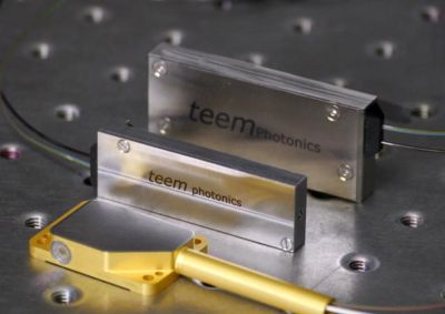
Teem Photonics has developed and offers the PicoMove interferometers — a new line of compact, stable and high performance interferometers for the measurement of picometer-scale displacements and vibrations.
These interferometers are based on single-chip integration of a high stability architecture which results in measurements with an intrinsic ultra-low noise.
The eye-safe operating wavelength of 1.55 µm provides compatibility with commercial telecom sources.

⚙ hardware
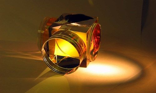
LightMachinery has a great breadth of expertise for manufacturing space qualified, wide-field Michelson interferometers.
Polarizing, non-polarizing, cemented, optically contacted (epoxy free bonded), hexagonal, square, small (1 mm), large (45 mm), UV, visible, IR. Material selection, coating design, modeling of phase & polarization, mechanical design, process development, quality planning, glass shaping and polishing, optical contacting, cementing and finally testing, testing and testing. Of course that's what makes it so interesting and challenging to work on these projects.

⚙ hardware
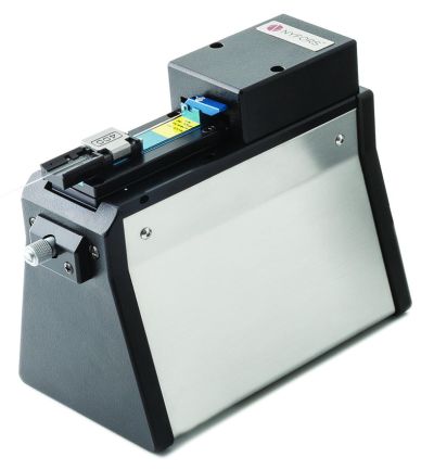
Nyfors offers high precision interferometers for checking the end face quality of cleaved optical fibers and for cleave process optimization. They show crisp and clear fringe patterns and come with software for advanced measurement functionality. Ideal for use in production settings and when working with difficult to cleave fibers in laboratory environments.
Fiber holder adaptors available for use with cleavers and splicers from the major splicer manufacturers. This facilitates easy transfer of the fiber from cleaver to interferometer and then onto the splicer with no need for reclamping.
Bibliography
| [1] | A. Labeyrie, “Stellar interferometry methods”, Am. Rev. Astrom. Astrophys. 16, 77 (1978); doi:10.1146/annurev.aa.16.090178.000453 |
|---|---|
| [2] | C. M. Caves, “Quantum-mechanical noise in an interferometer”, Phys. Rev. D 23 (8), 1693 (1981); doi:10.1103/PhysRevD.23.1693 |
| [3] | K. Creath, “Phase-shifting speckle interferometry”, Appl. Opt. 24 (18), 3053 (1985); doi:10.1364/AO.24.003053 |
| [4] | M. Xiao et al., “Precision measurement beyond the shot-noise limit”, Phys. Rev. Lett. 59 (3), 278 (1987); doi:10.1103/PhysRevLett.59.278 |
| [5] | M. T. Jaekel and S. Reynaud, “Quantum limits in interferometric measurements”, Europhys. Lett. 13, 301 (1990); doi:10.1209/0295-5075/13/4/003 |
| [6] | D. Shoemaker et al., “Prototype Michelson interferometer with Fabry-Perot cavities”, Appl. Opt. 30 (22), 3133 (1991); doi:10.1364/AO.30.003133 |
| [7] | P. Fritschel et al., “Demonstration of light recycling in a Michelson interferometer with Fabry-Perot cavities”, Appl. Opt. 31 (10), 1412 (1992); doi:10.1364/AO.31.001412 |
| [8] | S. Diddams and J.-C. Diels, “Dispersion measurements with white-light interferometry”, J. Opt. Soc. Am. B 13 (6), 1120 (1996); doi:10.1364/JOSAB.13.001120 |
| [9] | R. Dandliker et al., “Distance measurement by multiple-wavelength interferometry”, J. Opt. 29 (3), 105 (1998); doi:10.1088/0150-536X/29/3/002 |
| [10] | J. M. Schmitt, “Optical coherence tomography (OCT): a review”, J. Sel. Top. Quantum Electron. 5 (4), 1205 (1999); doi:10.1109/2944.796348 |
| [11] | J. D. Monnier, “Optical interferometry in astronomy”, Rep. Prog. Phys. 66 (5), 789 (2003); doi:10.1088/0034-4885/66/5/203 |
| [12] | A. Thüring et al., “Broadband squeezing of quantum noise in a Michelson interferometer with Twin-Signal-Recycling”, Opt. Lett. 34 (6), 824 (2009); doi:10.1364/OL.34.000824 |
| [13] | J. Biophoton. 2 (6-7) (2009): special issue on optical coherence tomography |
| [14] | J. Aasi et al., “Enhanced sensitivity of the LIGO gravitational wave detector by using squeezed states of light”, Nature Phjotonics 7, 613 (2013); doi:10.1038/nphoton.2013.177 |
| [15] | B. P. Abbott et al. (LIGO Scientific Collaboration and Virgo Collaboration), “Observation of gravitational waves from a binary black hole merger”, Phys. Rev. Lett. 116 (6), 061102 (2016); doi:10.1103/PhysRevLett.116.061102 |
| [16] | C. Hilweg et al., “Gravitationally induced phase shift on a single photon”, New J. Phys. 19, 033028 (2017); doi:10.1088/1367-2630/aa638f |
| [17] | K. U. Schreiber et al., “Variations in the Earth’s rotation rate measured with a ring laser interferometer”, Nat. Photon. 17, 1054 (2023); doi:10.1038/s41566-023-01286-x |
(Suggest additional literature!)

Questions and Comments from Users
Here you can submit questions and comments. As far as they get accepted by the author, they will appear above this paragraph together with the author’s answer. The author will decide on acceptance based on certain criteria. Essentially, the issue must be of sufficiently broad interest.
Please do not enter personal data here. (See also our privacy declaration.) If you wish to receive personal feedback or consultancy from the author, please contact him, e.g. via e-mail.
By submitting the information, you give your consent to the potential publication of your inputs on our website according to our rules. (If you later retract your consent, we will delete those inputs.) As your inputs are first reviewed by the author, they may be published with some delay.