A hemi-fission intermediate links two mechanistically distinct stages of membrane fission (original) (raw)
. Author manuscript; available in PMC: 2016 Feb 6.
Published in final edited form as: Nature. 2015 Jun 29;524(7563):109–113. doi: 10.1038/nature14509
Abstract
Fusion and fission drive all vesicular transport. Although topologically opposite, these reactions pass through the same hemi-fusion/fission intermediate1,2, characterized by a ‘stalk’ in which only the inner monolayers of the two compartments have merged to form a localized non-bilayer connection1-3. Formation of the hemi-fission intermediate requires energy input from proteins catalyzing membrane remodeling; however the relationship between protein conformational rearrangements and hemi-fusion/fission remains obscure. Here we analyzed how the GTPase cycle of dynamin, the prototypical membrane fission catalyst4-6, is directly coupled to membrane remodeling. We used intra-molecular chemical cross-linking to stabilize dynamin in its GDP•AlF4--bound transition-state. In the absence of GTP this conformer produced stable hemi-fission, but failed to progress to complete fission, even in the presence of GTP. Further analysis revealed that the pleckstrin homology domain (PHD) locked in its membrane-inserted state facilitated hemi-fission. A second mode of dynamin activity, fueled by GTP hydrolysis, couples dynamin disassembly with cooperative diminishing of the PHD wedging, thus destabilizing the hemi-fission intermediate to complete fission. Molecular simulations corroborate the bimodal character of dynamin action and indicate radial and axial forces as dominant, although not independent drivers of hemi-fission and fission transformations, respectively. Mirrored in the fusion reaction7-8, the force bimodality might constitute a general paradigm for leakage-free membrane remodeling.
Membrane fission and fusion both involve a pivotal stage, where lipids rapidly rearrange into a new topology under extreme protein-driven stress2,3. It is generally accepted that lipid rearrangements proceed in distinct steps, involving formation of transient highly-curved nonbilayer intermediate(s)9,10. How conformational changes of the protein machinery orchestrate this orderly remodeling of lipids remains unknown. This knowledge gap is highlighted in dynamin, the founding member of a superfamily of large GTPases implicated in membrane fission and fusion events4-6. Self-assembly of dynamin into helical structures around the necks of deeply invaginated clathrin coated pits and consequent stimulated GTPase activity drive conformational changes that underpin its role in catalyzing membrane fission and the release of clathrin-coated vesicles4,6. Crystallographic studies have provided multiple insights into the nature of these GTPase driven conformation changes. The N and C-terminal helices of dynamin's GTPase (G) domain, together with the C-terminal helix from the GTPase effector domain (GED), form a three helical bundle, termed the “bundle signaling element” (BSE) (Extended Data Fig. 1A). Crystal structures of a minimal G domain–BSE dynamin construct bound to either GMPPCP or the nucleotide transition-state analogue, GDP·AlF4- revealed two distinct conformations corresponding to a ~70° swing of the BSE relative to the G domain core (Fig. 1A, inset)11,12. Thus, akin to a lever arm in motor proteins13, it was proposed that BSE movements transmit and amplify transition state-dependent conformational changes in the G domain to affect intra- and/or inter-molecular conformational changes required for fission12. Observed only in the context of a minimal dynamin construct11,12, whether the dramatic nucleotide-dependent movement of the BSE occurs in the full-length protein and how it is transmitted to the membrane-interacting PHD and further to lipids are unknown.
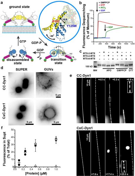
Figure 1. Stabilization of the transition-state conformer of dynamin.
a. Cartoon illustrating the mobility of BSE during dynamin's GTPase cycle, blue=apo/GDP-bound, yellow=GMPPCP-bound, yellow/blue=GDP·AlF4--bound transition-state. Inset shows BSE conformation in the crystal structures of GMPPCP- (yellow, PDB: 3ZYC) and GDP·AlF4- (blue, PDB: 2X2E)-bound G domain-BSE fusion protein. b. Loss of PET-dependent quenching of BODIPY fluorescence after addition of GMPPCP, GTP, or GDP either alone, or in the presence of AlCl3 and NaF (i.e. GDP·AlF4-). The decline in fluorescence signal in the presence of GTP reflect its hydrolysis. c. SDS-PAGE of CC-Dyn1 +/− crosslinker. The faster migrating CxC-Dyn1 is stabilized in the transition-state. d. Representative images showing membrane tubulation of SUPER templates (≥5 independent experiments) or GUVs (3 independent experiments) by CC- and CxC-Dyn1 in the absence of nucleotides. Images are inverted for clarity. e. Constriction (seen as dark patches) and fission activity of CC- and CxC-Dyn1 on fluorescently-labeled membrane tethers (see Videos S1 and S2; representative data from 3 independent experiments)) f. Fission activity assessed by vesicle release from SUPER templates of WT- (■) CC- (●), CxC-Dyn1 (△), and CxC-Dyn1 treated with DTT (▽) (average ±SD, n=3).
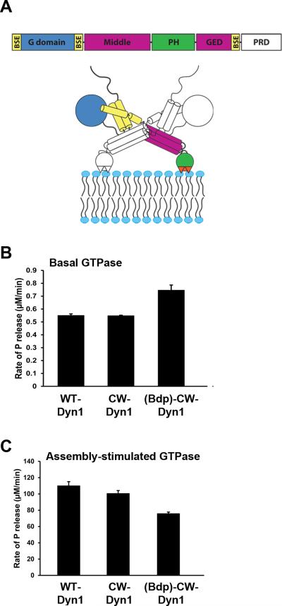
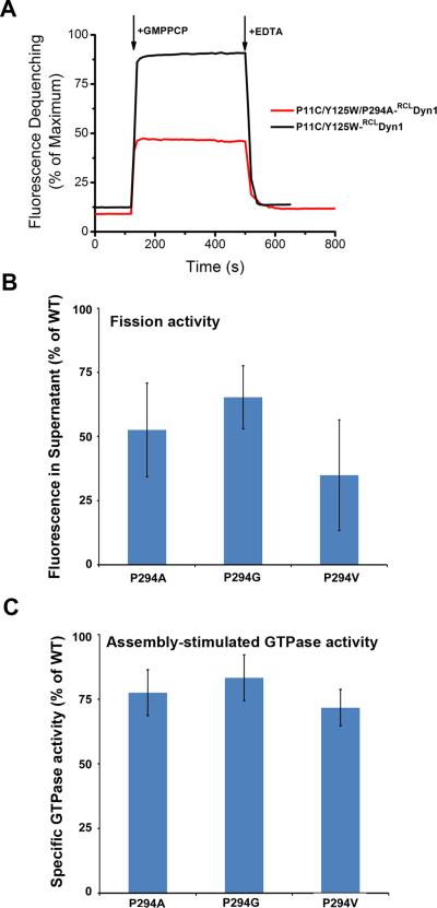
To gain insight into its functional consequences we utilized molecular engineering to access and control BSE motility in full-length wild-type dynamin 1 (WT-Dyn1). To detect BSE movements, we introduced Cys at position 11 into a functional reactive-Cys-less (RCL) derivative of WT-Dyn114 for site-specific labeling with a thiol-reactive BODIPY derivative and replaced Tyr at position 125 with Trp to yield CW-Dyn1 (Fig. 1A). This mutant and its BODIPY conjugate retained near-normal basal and assembly stimulated GTPase activities (Extended Data Fig. 1B,C). We employed photo-induced electron transfer (PET)15 that will result in the quenching of the BODIPY label in the BSE (Fig. 1A) by the Trp residue in the G domain only if the two moieties reside within a radius of ≤10 Å16 (Fig. 1A, inset). When bound to lipid nanotubes (Fig. 1B) the magnitude of PET-induced quenching of BODIPY varies in a nucleotide dependent manner, becoming progressively higher along the transition from the GTP-bound (stabilized by GMPPCP) to the GDP·AlF4—bound transition state. This behavior is consistent with the GTP-dependent BSE movement predicted by structural analyses (Fig. 1A)11,12, which further suggest that the BSE pivots around a Pro residue (P294) connecting the C-terminal helix of the G domain to the core12,17,18. Consistent with this, mutation of P294 reduces BSE motility and impairs both GTPase and fission activities of dynamin (Extended Data Fig. 2). Together, these data confirm that the BSE in full-length dynamin undergoes GTP-dependent conformational changes consistent with a rotation around P294 away from the G domain core.
We next applied site-specific crosslinking between the G domain and the BSE to stabilize the “transition-state” conformer. Trp125 in CW-Dyn1 was replaced with Cys to produce CC-Dyn1. Using a series of variable-length thiol-specific homo-bifunctional methanethiosulfonate (MTS) reagents, we identified MTS-4-MTS, which has a theoretical crosslinking span of 7.8 Å, as the shortest reagent able to yield ~100% crosslinking efficiency of CC-Dyn1, as evidenced by a gel shift to a faster migrating species (Fig. 1C). This is in good agreement with the distance separating the two Cys residues in the transition state (Fig. 1A). Hereafter, we refer to the cross-linked species as CxC-Dyn1.
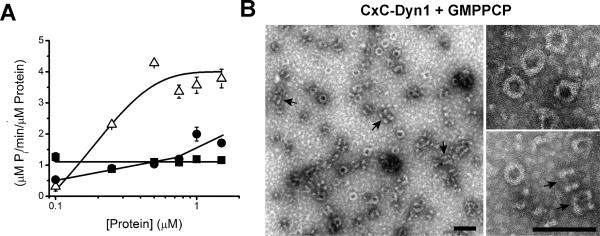
In solution, CxC-Dyn1 exhibited enhanced GTPase activity and self-assembled into rings, similar to GDP·AlF4--bound WT-Dyn1 (Extended Data Fig. 3A,B), verifying that crosslinking stabilizes the BSE at or near its “transition-state” conformation. CxC-Dyn1 retains the ability of WT-Dyn1 to produce high membrane curvature from flat lipid templates (Fig. 1D; Extended Data Fig. 4). Furthermore, like CC-Dyn1 (and WT-Dyn119), CxC-Dyn1 rapidly assembles on and tubulates membrane templates (Fig. 1E). However, unlike CC-Dyn1, CxC-Dyn1 failed to produce membrane fission either in the presence or absence of GTP (Fig. 1E, F; Supp. Videos 1 and 2). Reversal of the crosslink with DTT led to full recovery of fission activity (Fig. 1F), indicating that inhibition was due to disruption of dynamin's conformational changes and not to chemical modification of the cysteine residues.
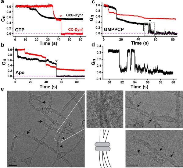
To determine at which stage fission is disrupted, we analyzed the membrane activity of CxC-Dyn1 by measuring protein-induced changes of the ionic conductance of the lumen of thin lipid nanotubes pulled from a planar reservoir membrane20,21. In the presence of GTP, CC-Dyn1 behaved like WT-Dyn121 causing a decrease in conductance due to nanotube constriction, followed (in 3 out of 3 cases) by an acute drop in conductivity to zero indicating complete closure of the tube lumen (Fig. 2A), which for WT-Dyn1 correlated with membrane fission21. In contrast, CxC-Dyn1 failed to trigger lumen closure in the presence of GTP in 11 out of 11 cases, although it retained the ability to constrict and lower nanotube conductance (Fig. 2A). In the absence of nucleotide (apo) or with GMPPCP (Fig. 2B and C), CC-Dyn1 produced stationary constriction but no lumen closure in 10 out of 10 cases and 3 out of 5 cases, respectively.
Figure 2. CxC-Dyn1 produces stable hemi-fission.
Representative traces of nanotube conductance changes in the presence of CC-Dyn1 (red traces) or CxC-Dyn1 (black traces) obtained in the presence (a) or absence (b) of GTP, or in the presence of GMPPCP (c, d). d. Expanded time-scale of the flickering hemi-fission phenotype, boxed in panel C. Gn indicates conductance normalized to the nanotube conductance before protein addition. e. Cryo-EM images (representative samples from 4 independent experiments) of CxC-Dyn1 assembled on PS liposomes in the presence of GMPPCP. Arrows indicate putative hemi-fission events detected by the loss of a defined inner leaflet of the bilayer occurring at sites of super-constriction (see inset). Scale bars 100 nm.
Surprisingly, CxC-Dyn1 in either the apo (Fig. 2B; 10 out of 12 cases) or GMPPCP-bound state (Fig. 2C; 8 out of 9 cases) produced complete closure of the tube lumen. These observations contrasted with the lack of scission of membrane tethers constricted by CxC-Dyn1 (Fig. 1E). The lumen closure could also correspond to hemi-fission, a state characterized by self-merger of the inner monolayer of the nanotube membrane without rupture of the outer one20,21. In support of this interpretation, we observed the occurrence of long-lived (up to seconds, Fig. 2D) flickering events that indicate reversible formation of a hemi-fission intermediate, both in the absence of nucleotide (3 out of 10 closure events) and in the presence of GMPPCP (Fig. 2C, D, 2 out of 8 closure events). Flickering events were also occasionally detected with WT-Dyn1, but these were highly transient intermediates (msec)21.
Cryo-EM analyses provided additional evidence for the formation of hemi-fission intermediates. Upon close examination of individual liposomes tubulated by CxC-Dyn1, we observed frequent examples of highly constricted tube segments in which the inner luminal diameter of the tube was no longer discernable (Fig 2E, arrows, insert). Such putative hemi-fission events were observed ~5 times more frequently in tubules decorated by CxC-Dyn1 (3.87±1.7/μm protein-coated tubes) as compared to CC-Dyn1 (0.86±1.3/μm protein-coated tubes). As the inner diameter can no longer be resolved at these putative sites of hemi-fission (Fig. 2E, inset), we measured their outer diameter (32±4.83 nm) and found that they were narrower even than that previously measured for the super-constricted tubes formed by K44A-Dyn1 in the presence of GTP (37 nm)22. Given that the latter had an inner lumenal diameter of 4 nm22, these data further support our conclusion that CxC-Dyn1 stabilizes a hemi-fission intermediate. Interestingly, long-ordered protein lattices were not observed at these sites, suggesting that the hemi-fission transformation is predominantly driven by small protein oligomers22.
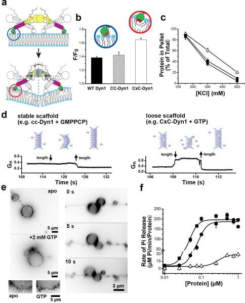
The ability of CxC-Dyn1 to generate hemi-fission in the absence of nucleotide suggests that conformational changes in the BSE are somehow transmitted through the stalk to the PHD to alter dynamin-membrane interactions and enhance its ability to remodel membranes (Fig. 1A, 3A). To test this we measured the nature of dynamin-membrane interactions using FRET between Trp residues in the PHD and Dansyl-lipid containing target membranes23. CxC-Dyn1 exhibited a nearly 20% increase in the Dansyl fluorescence emission upon Trp excitation compared to either WT- or CC-Dyn1 (Fig. 3B, Extended Data Fig. 5A), suggesting increased membrane penetration of the PHD in the transition-state. Consistent with this interpretation, membrane binding of CxC-Dyn1 also displayed a decreased sensitivity to salt extraction (Fig. 3C), indicative of increased hydrophobic vs. electrostatic interactions with the membrane23. Together these data provide direct evidence for the enhanced “membrane wedging” activity of transition-state dynamin (Fig. 3B, insets).
Figure 3. CxC-Dyn1 displays enhanced membrane wedging activity and altered scaffolding properties.
a. Cartoon illustrating transmission of transition-state BSE conformational information through the stalk to the PHD. b. FRET between PHD Trps and Dansyl-lipids measuring the relative membrane insertion of CC- and CxC-Dyn1 (average ±SD, n=3) (see Extended Data Figure 5 for complete spectra). c. Hydrophobic character of membrane insertion of WT-Dyn1 (■), CC-Dyn1 (●), and CxC-Dyn1 (△) measured by resistance to salt extraction. (average ±SD, n=3) d. Differential behavior of nanotubes to vertical displacement of the patch-pipette depending on the nature/persistence of the protein scaffold. Long scaffolds formed by WT or CC-Dyn1 in the presence of GMPPCP prevent retraction of the nanotube into the reservoir when shortened, and hence no change in tube conductance (left panel). Short/flexible scaffolds formed by CxC-Dyn1 in the presence of GTP allow free movement of membranes back into the reservoir, with concomitant increase in conductance (right panel). e. Addition of GTP to GUVs previously tubulated by preassembled CxC-Dyn1 (3 independent experiments) promotes tubule retraction towards the vesicle membrane. The tubules remain constricted during retraction (see Video S3). Images are inverted for clarity. f. Concentration dependence and cooperativity of the assembly-stimulated GTPase activity of WT-Dyn1 (■), CC-Dyn1 (●), and CxC-Dyn1 (△) measured on 100 nm PIP2-containing liposomes (average ±SD, n=3).
The hemi-fission activity of CxC-Dyn1 in the apo state contrasts with its inability to produce either hemi-fission or complete fission in the presence of GTP (Fig. 2A-D). To understand this paradoxical effect of GTP on CxC-Dyn1, we further examined the nature of the membrane constriction produced by CxC-Dyn1. The nanotube conductance characterizing stationary membrane constriction produced by CxC-Dyn1 in the presence of GTP (0.22+/−0.1 Gn) was comparable to that produced by CC-Dyn1 (to 0.27+/−0.05 Gn) in the absence of nucleotide (Fig. 2A, B). Such tight membrane constriction is traditionally associated with polymerization of a rigid helical scaffold that, as with CC-Dyn1, prevents retraction of the underlying constricted nanotube to the reservoir21 and an accompanying increase in the tube conductance (Fig. 3D, left). In contrast, the length of the nanotube constricted by CxC-Dyn1 could be freely decreased in the presence of GTP, seen as an increase in conductance (Fig. 3D, right). This “weakening” of the dynamin scaffold by GTP can be associated with GTP-driven depolymerization and/or loosening of the scaffold14,20. Indeed, addition of GTP to tubes produced by CxC-Dyn1 from GUVs or SUPER templates caused their partial retraction, while they remained constricted (Fig. 3E, Supp. Video 3). Moreover, the GTPase activity of membrane-bound CxC-Dyn1 (Fig. 3F) is significantly reduced relative to WT- or CC-Dyn1, but its membrane binding is unaffected. Importantly, CxC-Dyn1 is no longer released during GTP hydrolysis (Extended Data, Fig. 5B,C). Together these data suggest that although GTP induces depolymerization, the impaired hydrolysis and enhanced membrane interactions of CxC-Dyn1 prevent its release from lipid templates in the presence of GTP. The resulting loosened scaffolds retain their curvature activity but fail to produce hemi-fission, corroborating the notion that formation of this fission intermediate requires a critical degree of dynamin oligomerization, e.g. a single rung of 2-start helix21,22.
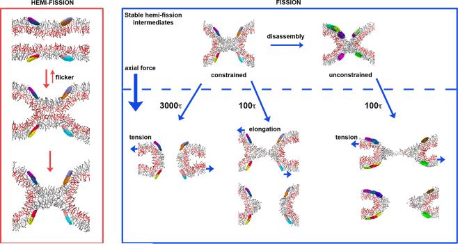
To test the generality of our findings that localized membrane constriction by a short membrane-inserting scaffold yields stable hemi-fission but not complete fission, we applied coarse-grained computer simulations previously used to analyze membrane fusion24,25, and more recently dynamin-mediated membrane fission26. In the latter case, the main stages of the fission process were remarkably well reproduced by simple constriction of a cylindrical lipid bilayer using a system of amphiphilic disks arranged in rings26 (Extended Data Fig. 6, 7). Intriguingly, ring constriction could not bring the simulations past the hemi-fission state26. To obtain mechanistic insights into this disruption of the fission reaction, we further analyzed the structure and stability of the hemi-fission intermediate using similar simulation modeling. Closely imitating the localized constriction of the membrane nanotube by CxC-Dyn1 (Fig 4A, Extended Data Fig. 6A,B), we induced self-mergers of the inner monolayer of the tube that further developed into an extended wormlike-micelle structure (Fig. 4A, Extended Data Fig. 6B). The micelle geometry was reproducible in different simulation runs (L=9.0±0.9 nm, SD, n=8, pairs taken from 4 independent simulation runs). These micelles remained stable throughout the observation period even under application of moderate membrane tension (see Methods: Molecular Simulations). Relaxation of the geometric constraints imposed by the ring system (ring “disassembly”26) caused shortening of the micelle (to L=5.2±0.6, SD, n=10) without rupture (Extended Data Figure 6, 7), demonstrating that the hemi-fission intermediate does not spontaneously rupture even in the absence of the protein support. Hence, as for membrane fusion25, completion of the fission reaction requires additional energy input to overcome the intrinsic lipid resistance and the stabilizing effect of the protein scaffold.
Figure 4. The two stages of dynamin-catalyzed membrane fission.
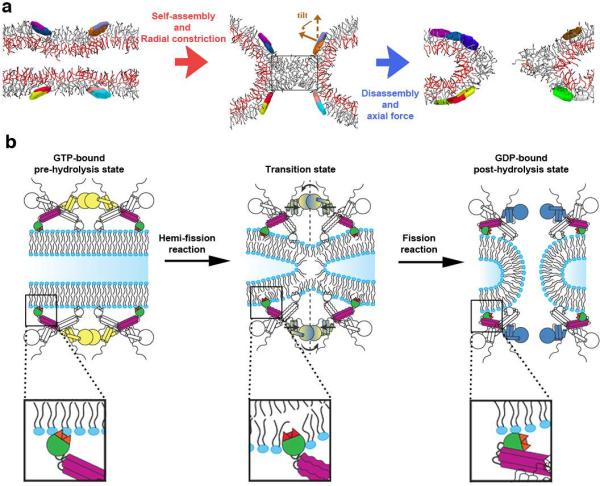
a. Coarse-grained simulations revealed formation of a stable hemi-fission intermediate (cylinder-like lipid micelle, middle panel) separating the two different stages of membrane fission. Axial cross-sections of representative snapshots from the simulation runs are shown. Localized radial constriction of a membrane tube by a 2 protein-mimetic ring system (effective radius 5-6 nm, inter-ring distance ~10nm) triggered hemi-fission reaction (red arrow). The tilt characterizes the local membrane orientation imposed by the disks26 (see Extended Data Fig. 6A for the ring description). The micelle intermediate remained stable under simulation conditions (see Extended Data Fig. 7) unless a moderate axial force was applied to cause its rupture, thus completing the fission reaction (blue arrow). The rectangular box indicates the dimensions of the cylindrical micelle (~9 × 5.5nm). b. Model of distinct dynamin activities and conformational changes mediating the two-stages of dynamin-catalyzed membrane fission that are required to form the metastable hemi-fission intermediate and then to drive full fission (see Extended Data Fig. 8).
This input apparently comes from GTP hydrolysis. Importantly, the connection between the G domains and PHD, mediated by BSE and disrupted in CxC-Dyn1, is required to deliver the energy to the hemi-fission intermediate. It is unlikely that this GTP hydrolysis-driven conformational change causes additional membrane constriction because progression of the GTP cycle past the transition state diminishes the curvature activity of dynamin20 and structural studies clearly associate membrane super-constriction with the pre-transition-state dynamin conformer22. Interestingly, in computer simulations, application of moderate (~0.6 Dyn/cm) membrane tension27 in combination with ring disassembly produced immediate rupture of the hemi-fission intermediate. The combination of 10-fold weaker tension and a gradual increase of the separation between rings (e.g. due to abrupt loosening of the scaffold28) also mediated the transition from hemi-fission to complete fission (Extended Data Fig. 7). Although the mechanics of this transition require further investigation, our data suggest that they differ from radial constriction and likely involve production of an axial force in coordination with disassembly of the dynamin scaffold.
These findings demonstrate that dynamin implements different strategies while mediating sequential topological transitions of inner and outer monolayers for fission (Fig. 4B, Extended Data Fig. 8). This bimodality, which is likely embedded in the molecular design of the proteins that catalyze fission and fusion may constitute a fundamental feature required to coordinate the two-step non-leaky reactions with lipids. It is tempting to speculate that the current controversies regarding mechanistic models of dynamin4-6 are related to the previously unappreciated bimodal nature of the process. That is, the different models may reflect sequential modes of dynamin action required for formation and rupture of hemi-fission.
METHODS
Protein expression and purification
Sf9 insect cells were transiently transfected with cDNAs encoding wild-type human Dynamin-1 or indicated mutants subcloned in pIEx-6 vector (EMD Millipore, Billerica, MA) for protein production. Proteins were purified by affinity chromatography using GST-tagged Amphiphysin-II SH3 domain as an affinity ligand as described previously28. Purified proteins were dialyzed overnight in 20 mM Hepes (pH 7.5), 150 mM KCl, 1 mM EDTA, 1 mM DTT, and 10% (v:v) glycerol, aliquoted, flash-frozen in liquid N2, and stored at −80 °C. Protein concentrations were determined by absorbance at 280 nm using a molar absorptivity coefficient of 59,820 M−1 cm−1 for P11C/Y125W-RCLDynamin-1 and P11C/Y125W/P294A-RCLDynamin-1, 54,445 M−1 cm−1 for P11C/Y125C-RCLDynamin-1, and 56,185 M−1 cm−1 for other Dynamin-1 proteins.
Protein labeling
The Cys residues at positions 11 in P11C/Y125W-RCLDynamin-1, P11C/Y125W/P294A-RCLDynamin-1, and 752 in T752C-RCLDynamin-1 were selectively labeled in the absence of reducing agent using tenfold molar excess of the thiol-reactive iodoacetamide derivative of BODIPY-Fl (Life Technologies, Grand Island, NY). After 30 min incubation at room temperature, DTT was added to 5 mM to quench the reaction. The solution was extensively dialyzed against buffer containing 20 mM HEPES (pH 7.5), 150 mM KCl, 1 mM EDTA, and 1 mM DTT to separate unreacted dye molecules. Following high-speed ultracentrifugation (100,000 × g) to discard any precipitated protein, the efficiency of labeling was determined using a molar absorptivity coefficient of 76 000 M−1 cm−1 at 502 nm for BODIPY.
Protein crosslinking
MTS-based homobifunctional crosslinking reagents were obtained from Toronto Research Chemicals (Toronto, Canada). Unless otherwise indicated, crosslinking of P11C/Y125C -Dynamin-1 was carried out at room temperature for 15-30 min with 50 μM MTS reagents. The theoretical spanning distance of MTS reagents was derived from ref. 29. For visualization of the crosslinked proteins all unreacted Cys residues were blocked by 10 mM N-ethylmaleimide prior addition of 6× SDS sample buffer. Samples were subsequently resolved on a 7.5% polyacrylamide gel followed by Coomassie staining. For reversal of crosslinking samples were incubated for 30 min on ice with 20 mM DTT.
Preparation of liposomes, lipid nanotubes, and SUPER templates
1,2-dioleoyl-_sn_-glycero-3-phosphocholine (DOPC), 1,2-dioleoyl-_sn_-glycero-3-phospho-(1′-_rac_-glycerol) (DOPG), 1,2-dioleoyl-_sn_-glycero-3-phosphoethanolamine (DOPE), 1,2-dioleoyl-_sn-_glycero-3-phospho-L-serine (DOPS), L-α-phosphatidylinositol-4,5-bisphosphate (PIP2), 1,2-dioleoyl-_sn_-glycero-3-phosphoethanolamine-_N_-(lissaminerhodamine B sulfonyl) (RhPE), 1,2-dioleoyl-_sn_-glycero-3-phosphoethanolamine-N-(5-dimethylamino-1-naphthalenesulfonyl (Dansyl-PE), and C24:1 β-D-galactosylceramide (GalCer**)** were purchased from Avanti Polar Lipids (Alabaster, AL). Cholesterol was from Sigma-Aldrich (St. Louis, MO). Appropriate amounts of lipid stock solutions were mixed in a glass tube to obtain the desired compositions. The solvent was removed under a gentle stream of nitrogen and the lipid residue was subsequently maintained under a reduced pressure for 1-2 hours. The dry lipid film was hydrated for 30 min at room temperature in Milli-Q H2O (for preparation of SUPER templates) or 20 mM HEPES (pH 7.5), 150 mM KCl and subjected to three freeze–thaw cycles. The resulting suspensions of multilamellar vesicles were extruded through polycarbonate membranes of varying pore diameters to yield unilamellar liposomes of desired size. Lipid nanotubes composed of DOPC:DOPS:PIP2:GalCer (40:15:5:40) were generated using a bath sonicator according to procedures described previously30. Supported bilayers with excess membrane reservoir (SUPER) templates were prepared as previously reported19,31, with minor modifications. Briefly, an 20 μl aliquot of an aqueous suspension (5% w:w) of 2.5 μm diameter silica microspheres (Corpuscular, Cold Spring, NY) was added to a NaCl-containing solution of 100 nm liposomes (DOPC:DOPG:DOPE:DOPS:PIP2:RhPE = 19:40:20:15:5:1) for a total volume of 100 μl (with final lipid and NaCl concentrations of 200 μM and 300 mM, respectively) in a 1.5 ml low-adhesion polypropylene centrifuge tube (USA Scientific, Ocala, FL). This mixture was incubated for 30 min at room temperature with intermittent mixing. The templates were subsequently washed four times with 1 ml of Milli-Q H2O by a low-speed spin (260 g) for 2 min in a swinging-bucket rotor at room temperature, leaving behind after each wash a 100 μl volume for resuspension of the pelleted templates.
GTPase assay
Basal and assembly-stimulated GTP hydrolysis rates of wild-type and mutant dynamins were measured using Malachite Green –based colorimetric assay that detects the inorganic phosphate released during the time-course of the reaction30. Briefly, indicated concentrations of proteins were incubated at 37°C in the absence (basal) or presence of (assembly-stimulated) 100 nm liposomes prepared with DOPC:DOPS:PIP2 = 80:15:5 (total lipid conc. = 150 μM) in a buffer containing 20 mM Hepes (pH 7.5), 150 mM KCl, 1 mM MgCl2, and 1 mM GTP (Jena Bioscience, Jena, Germany). 20 μl aliquots were drawn from the reaction mixtures at several time-points and transferred to wells of a 96-well microplate containing 5 μl 0.5 M EDTA, thereby quenching the hydrolysis reaction. 150 μl of Malachite Green stock solution was added to each well and the absorbance at 650 nm was measured using a microplate reader. Free phosphate was determined from the absorbance values using a standard curve. The initial rates of GTP hydrolysis were calculated from the linear phase of the time-course.
Preparation of GUVs, planar bilayer lipid membranes (BLMs), and nanotubes from BLMs
GUVs were formed by spontaneous swelling of lipid films deposited on 40 μm silica beads. Briefly, DOPC:DOPE:DOPS:Chol:PIP2:RhPE 28:24:15:30:2:1 mixture in chloroform (0.05 mg total lipid) was dried in vacuum for 1 h. Then the mixture was rehydrated by adding 10 μL of 1 mM Hepes buffer, pH 7.0. After vigorous mixing, the multilamellar lipid solution was doped with 40 μm plain silica beads and deposited on a Teflon film as 4-5 drops of ~2 μL and then vacuum-dried for 30 min. The beads covered by lipid film were picked from the Teflon film by a thin glass pipette, pre-hydrated for 5 min under H2O saturated N2 atmosphere, and then added from the top to a vertically placed plastic pipette tip filled with 5 μL of a pH-buffered sucrose solution. GUVs formed spontaneously on the bead surface upon 10 minutes of gentle hydration at 60°С. Then the lower end of the tip was briefly immersed into a home-made observation chamber filled with 1 mL of buffer (150 mM KCl, 10 mM Hepes, 1 mM EDTA, 2 mM MgCl2), thus transferring the beads with the attached and detached GUVs into the chamber. The 0.13-0.16 mm thick cover glass of the chamber was pretreated with bovine serum albumin (BSA) solution (0.1 g/L, 5 min at room temperature) to inhibit lipid attachment to the glass surface. GUVs were further monitored by fluorescence microscopy, as described below.
Bilayer lipid membranes were formed from the same lipid composition as GUVs on an gilded copper grid (mesh 200, Agar Scientific, Essex, UK) pretreated with the same lipid mixture (10 g/L total lipid) dissolved in decane:octane (1:1 v/v): a small drop of the mixture was deposited across the grid and the solvents were then evaporated under argon stream. The grid was mounted on the bottom of an observation chamber which was subsequently filled with the buffer containing 150 mM KCl, 10 mM Hepes, 1 mM EDTA, 2 mM MgCl2. Finally, a small amount of lipid mixture in squalane (20-30 g/L, total lipid) was “painted over” the grid using a thin brush. Lipid bilayers formed spontaneously on each mesh covered by a thick film deposited by the brush. The excess lipid material, expelled to the periphery of the mesh, formed a toroidal meniscus maintaining the lateral tension of the lipid bilayer.
Lipid membrane nanotubes were pulled from the parent BLM using a nano-positioning system based upon high-resolution NanoPZ actuators (Newport Corp., Stratford, CT) and calibrated piezo-micromanipulator (Newport; 30 mm travel). Fire-polished borosilicate patch-pipettes (the tip diameter of ~1 mm) were used for pulling. The tube formation and manipulation were performed as described earlier20,21. Protein were delivered with a second micropipette, back filled with 7 mM solution of the CC- or CxC-Dyn1 solution in 150 mM KCl, 20 mM Hepes, 1 mM EDTA, and 2 mM MgCl2. For experiments made in presence of nucleotide, the nucleotides were added in equal concentration both to the observation chamber and the protein delivery pipette.
Fission assay
The efficiency of wild-type and mutant dynamins to catalyze the release of membrane vesicles from RhPE-labeled SUPER templates was analyzed by means of a sedimentation assay, as described elsewhere19,31. In brief, an aliquot of template suspension was added without mixing to a final volume of 100 μl of 20 mM HEPES (pH 7.5), 150 mM KCl, with 1 mM MgCl2, 1 mM GTP, and indicated protein concentrations. The samples were left undisturbed for 30 min at room temperature, the templates subsequently pelleted at 260 × g for 2 min and the supernatants mixed with Triton X-100 to dissolve released vesicles. Total membrane fluorescence of templates was determined in a separate reaction by adding equal amount of templates to Triton X-100 prior to pelleting. The fluorescence intensity of the supernatants was read on 96-well plates using a plate reader (Bio-Tek Instruments, Winooski, VT) with excitation and emission monochromators set at 530/25 and 590/25 nm, respectively.
Sedimentation assay
Self-assembly of wild-type and mutant dynamins and their GTP hydrolysis –triggered disassembly were assessed by sedimentation following high-speed centrifugation. Two identical sets of samples were prepared by incubating dynamin (1 μM) for 30 min with or without 400 nm DOPS liposomes (total lipid conc. = 300 μM) in 20 mM HEPES, (pH 7.5), 150 mM KCl, 1 mM MgCl2 in a final volume of 30 μl at room temperature. 1 mM GTP or GMPPCP was added to one set of samples and both sets were transferred to a 37°C water bath for 5 min. Mixtures were then spun at 20 800 × g for 20 min in a microfuge refrigerated at 4°C to obtain supernatant (S) and pellet (P) fractions. The pellet fraction containing liposomes and assembled protein was resuspended in 30 μl of the same buffer to obtain equal volumes of S and P fractions. Samples were subsequently resolved on a 7.5% polyacrylamide gel and visualized by Coomassie staining to evaluate protein levels. Dynamin self-assembly on 100 nm DOPC:DOPS:PIP2 = 80:15:5 liposomes in the absence of GTP was quantified using identical approach.
Fluorescence spectroscopy
All fluorescence measurements were carried out with 0.1 μM BODIPY-labeled P11C/Y125W-RCLDynamin-1 or P11C/Y125W/P294A-RCLDynamin-1 in buffer containing 20 mM HEPES (pH 7.5), 150 mM KCl, and 1 mM MgCl2 using a Fluorolog-3 photon-counting steady-state spectrofluorometer (Horiba Jobin Yvon, Edison, NJ) equipped with double excitation and emission monochromators, a cooled PMT housing, and a 450 W xenon lamp. Samples (2.4 ml final volume) were prepared in 10 mm path length quartz cuvettes held at 25°C and continuously stirred with a magnetic stir bar during data acquisition. Where indicated, dynamin was incubated with PIP2-containing lipid nanotubes (1:300 molar ratio of protein to lipid) for 10 min to induce self-assembly. In PET experiments BODIPY was excited at 490 nm (2.5 nm bandpass) and emission was monitored at 510 nm (2.5 nm bandpass) with fluorescence intensity values recorded at 10 s intervals (5 s signal integration). Nucleotides or AlCl3 (1 mM final concentration) were added to the cuvette at indicated time-points. For experiments involving GDP·AlF4-, 10 mM NaF was added to the buffer before data collection was initiated. Concentration-matched sample of BODIPY conjugated to T752C-RCLDynamin-1 was utilized to establish level of BODIPY emission intensity corresponding to complete loss of PET-induced quenching.
FRET between PH domain tryptophans and Dansyl-PE containing 400 nm liposomes (DOPS:Dansyl-PE = 90:10) was used to investigate membrane interaction of dynamin proteins, as described elsewhere23. Briefly, 2.4 ml samples composed of either 0.1 μM protein (donor only) or 5 μM lipid (acceptor only) were excited at 280 nm (2 nm bandpass) and their emission spectra recorded between 315 and 550 nm (4 nm bandpass). Increase in Dansyl fluorescence due to FRET was monitored at 515 nm in samples containing both donor and acceptor following a 20 min incubation. Data in Figure 3 are presented as F/F0, where F0 corresponds to fluorescence intensity of Dansyl-labeled liposomes in the absence of FRET donors, and F is the intensity measured.
Fluorescence microscopy
Fluorescence imaging of RhPE-labeled SUPER templates was performed in BSA-coated Nunc Lab-Tek chambered microscope slides (Thermo Scientific, Waltham, MA) using a Nikon Eclipse Ti (Nikon instruments, Melville, NY) inverted microscope equipped with a 100×, 1.45-NA oil-immersion objective and ORCA-Flash 4.0 CMOS camera (Hamamatsu, Middlesex, NJ). An aliquot of template suspension was added to 200 μL 20 mM Hepes (pH 7.5), 150 mM KCl, 1 mM MgCl2 in the presence or absence of indicated nucleotides (1 mM final concentration) and allowed to settle to the bottom of the chamber. For curvature generation (tubulation) experiments 0.5 μM dynamin was added to the observation chamber before templates, and imaging was performed following 10-15 min incubation at room temperature. Membrane tethers were generated by rolling 20 μm silica beads over the surface of the SUPER templates through tilting of the observation chamber31.
The GUVs were monitored using an Olympus IX-70 inverted microscope (150×, 1.45-NA objective) equipped with AndoriXon+ camera (Andor Technology, Belfast, UK). A halogen lamp was used as the excitation source, ensuring minimal photobleaching, 550/590 nm excitation/emission wavelengths were used. All images were collected and processed using the ImageJ-μManager open source software32.
Electron microscopy
For negative stain EM, samples (1-3 μM dynamin and 200 μM DOPS liposomes incubated in the presence or absence of 1 mM GTP or GMPPCP for 30 min at room temperature) were absorbed onto carbon-coated 400 mesh Cu/Rh grids (Ted Pella, Inc.), stained with 2% Uranyl Acetate, and imaged in a Tecnai 12 (FEI) transmission electron microscope at 120kV using a 2 × 2 Gatan CCD camera. For cryo-EM, a 3.5 μl sample (prepared as described above) was placed on a plasma-cleaned (Fishione Inc.). Quantifoil holey carbon EM grid (SPI Supplies), blotted with filter paper, and flash-frozen in liquid ethane using a Leica EM GP (Leica Microsystems). The grids were subsequently stored in liquid nitrogen. The vitrified samples were imaged at liquid nitrogen temperature on a Tecnai 20 FEG electron microscope (FEI) operating at 200kV and images were collected with a 4 × 4 CCD camera.
Measurement of conductance through lipid nanotubes
The equivalent electrical circuit for nanotubes pulled from planar BLMs has been described earlier20. The nanotube conductance was measured at 50-100 mV holding potential using Axopatch 200B (Molecular Devices, Sunnyvale, CA) amplifier. The signal was digitized using a PC-44 acquisition board (Signalogic, Dallas, TX) as described earlier20. The current was acquired at voltage-clamp mode of the amplifier, collected using the acquisition board and processed off-line using Origin software (OriginLab, Northampton, MA). The measured conductance of the nanotube in the presence of the protein was normalized to the conductance level measured for the nanotube just before protein addition.
Molecular Simulations
The simulation method33 and the model parameters34 used were as previously described26,33,34. The simulations were conducted using a molecular dynamics scheme with a dissipative particle dynamics thermostat33,35,36. The simulations were performed in an ensemble that allows the length of the simulation box along the axis of the lipid cylinder to dynamically vary during the simulations in order to keep the tension in that direction constant.
Lipid Model
Our simulations use a coarse-grained, solvent-free lipid model26,33,37 in which the lipids are represented as linear chains comprised of two polar head-group particles and eight hydrophilic tail particles. The particles are connected by a harmonic bond potential and a soft bond-angle potential, while the non-bonded interactions are based on a third-order weighted-density functional of the particle densities. This model was shown to successfully reproduce elastic and dynamic properties of lipid bilayers33,38 as well as lipid phase behavior and topological transitions33,34.
Cylindrical bilayers
The cylindrical tubes of lipid bilayers were assembled by using estimates for the number of lipids in the inner and outer monolayer based on their radii. These configurations were then relaxed by simulating the system in an ensemble that allowed the cylinder length to dynamically vary, keeping the tension along the cylinder axis at zero, resulting in a radius of 6.2 nm and a inside-to-outside lipid ratio of 126:205. The cylinders used in our simulations had a length of 38.8 nm at zero axial tension and consisted of 7200 lipids.
Peptide model
In order to explicitly test the effects of the insertion of the PH domains of the dynamin complex, we modeled the PH domains as amphiphilic hexagonal disks consisting of one layer of polar particles connected to one layer of hydrophilic particles. Each layer had three particles per edge and an edge length of 1.3 nm, and the two layers had a separation of 0.6 nm. The particles in each peptide disk were held together by a network of stiff, elastic bonds26.
Constriction of membrane cylinder by the peptide rings
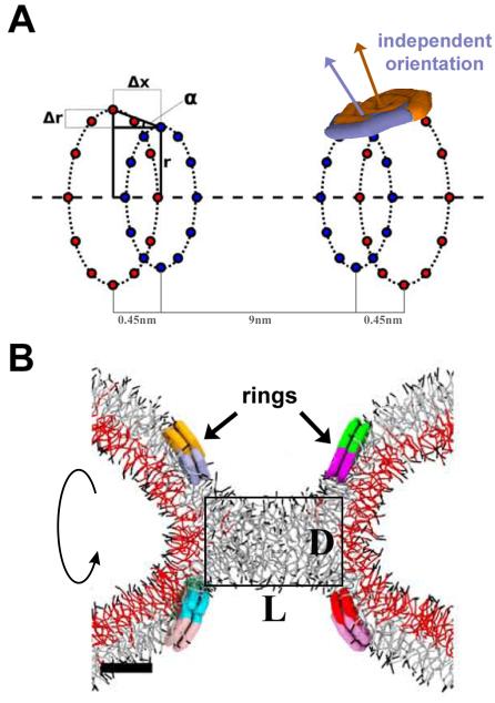
In order to constrict the lipid cylinder, we arranged the peptide disks into the ring system described earlier26 Twelve disks were restrained at positions equally distributed on a ring forming a belt around the cylindrical lipid bilayer (Ext. Data Fig. 6A). Only the disks’ centers of mass were restrained, while the orientations of the disks could freely change in response to interactions with the lipids. To represent one 'rung' of the dynamin spiral formed by the protein dimers[8], we used pairs of such rings separated by 0.45 nm (Δx). This distance was smaller than the disk size so the disks from the juxtaposed rings overlapped while preserving their independent mobility (Ext. Data Fig 6A). This way the disk pair created a flexible membrane-interacting surface imitating adaptive membrane wedging by a pair of PH domains of dynamin dimer. The radius of one of the two juxtaposed rings was slightly smaller (Δr=0.45-0.9nm) so that the disk pair exerted a direct influence on the orientation of the membrane at the location of the peptides thus stimulating formation of an hourglass shaped lipid morphology26. Two of the juxtaposed ring pairs situated 9 nm apart (separation between the inner rings corresponding to ~10nm separation between the midpoints of the ring pairs) constituted the ring system used in simulations (Ext. Data Fig. 6A).
In simulations with restrained disks, the ring radii and the separation between the rings were fixed and the position of the disks on the rings were tied to their respective anchor points with a harmonic potential26. In the experiments with gradually changing separation between the rings, we fixed the position of one ring pair and slowly moved the other pair away along the axis of the membrane cylinder. In other simulations, we effectively “_disassemble_” the rings by omitting the positional restraints and allowing the disks to move freely along the membrane surface after the stable hemi-fission intermediate has formed.
A more detailed description of the peptide model and the simulation setup can be found in ref 26.
Stability of the wormlike micelle hemi-fission intermediate
The time unit in our simulations, obtained from the self-diffusion coefficient for lipid at room temperature34, was τ=2ns. The characteristic time for a local relaxation process in the cylindrical bilayer system described can be estimated as ~100τ26. The total lifetime of the wormlike micelle obtained in the restrained system (9 nm ring separation) under zero tension was 30200τ (4 independent simulations). Disassembly of the rings did not produce rupture of the micelle (5900τ). To probe the stability of this unrestrained system we applied small axial tension. The system remained stable for 18200τ under 0.06Dyn/cm tension (Ext. Data, Fig 7, 3 independent simulations) and for 15800τ under 0.12Dyn/cm tension (2 independent simulations) indicating that moderate membrane tensions are not sufficient to make the hemi-fission intermediate unstable. From the hemi-fission lifetime, the lower boundary for the barrier can be estimated to be on the order of ~10kBT; however, the exact pathway(s) of the membrane transformations leading to complete fission and the corresponding free energy profiles require further investigation.
Rupture of the hemi-fission intermediate
To induce rupture of the pre-formed hemi-fission intermediate we applied an axial tension of 0.6 Dyn/cm, typical for the planar bilayer systems used in the experiments. This tension produces immediate (lifetime <100τ, 5 independent simulations) rupture in the unrestrained systems and also destabilized the restrained systems, although much less efficiently (lifetime of 3400±1400τ, SD, 3 independent simulations). To augment the effect of tension we add an additional axial force-factor by slowly (~0.03nm/τ) increasing the separation distance between the two double rings. This ring movement augmented the tension effect so that immediate rupture (<100τ, 3 independent simulations) was produced under 0.06 Dyn/cm tension. The pathways of the hemi-fission rupture explored here are summarized in Ext. Data Fig. 7.
Extended Data
Extended Data Figure 1. Domain structure and biochemical characterization of dynamin constructs.
A. Domain structure of dynamin and cartoon illustrating that the GTPase domain (G domain, blue) connects through the bundle signaling element (BSE), composed of the N- and C-terminal helices of the G domain and the C-terminal helix from GED (yellow), to the stalk formed by the middle domain and GED (magenta). The pleckstrin homology domain (PHD, green) interacts with membrane lipids. B. Basal and C. assembly-stimulated rates of GTP hydrolysis rates for 0.5 μM WT and CW-Dyn1 before and after BODIPY conjugation (Data shown as average ±SD, n=3)
Extended Data Figure 2. Role of P294 in BSE conformational dynamics.
A. Changes in emission intensity of BODIPY-labeled CW-Dyn1 and P294A-CW-Dyn1 due to loss of PET following addition of 1 mM GMPPCP. Although the BSE partially opens upon addition of GMPPCP, its movements are constrained relative to WT by the mutation of P294. B. Assembly-stimulated GTPase activity of 0.5 μM P294A, P294G and P294V-Dyn1 measured on 100 nm liposomes relative to WT-Dyn1. The mutants show near WT activity indicating their ability to self-assemble onto and tubulate liposomes (data shown as average ±SD, n=4). C. Fission activity of 0.5 μM P294A, P294G and P294V-Dyn1 relative to WT-Dyn1 measured as the percentage of total membrane released from SUPER templates during 30 min incubation in the presence of GTP (Data shown as average ±SD, n=3). Substitution of P294 with the more rigid valine residue has a greater effect on fission activity.
Extended Data Figure 3. Characterization of CxC-Dyn1.
A. Concentration dependence of the specific GTPase hydrolysis rates of WT-Dyn1 (solid squares), CC-Dyn1 (solid circles), and CxC-Dyn1 (open triangles) measured in solution at 1 mM GTP (Data shown as average ±SD, n=3). B. EM micrographs (representative images from 4 independently prepared samples) showing CxC-Dyn1 assembled into rings and short spirals (arrows) in the presence of GMPPCP visualized by negative stain. Insets: top view, rings; side view, short spirals (arrows). Unlike, CxC-Dyn1, CC-Dyn1 remained unassembled in the presence of GMPPCP (data not shown). Scale bars 100 nm.
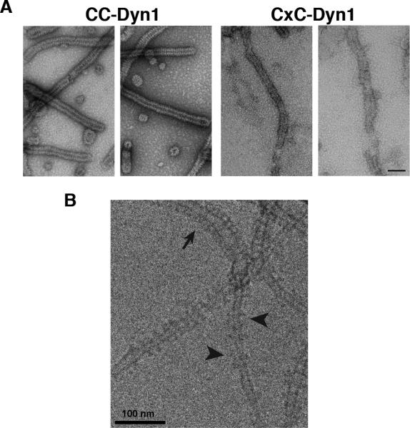
Extended Data Figure 4. Negative stain (A) and cryo-EM (B) images of CC- and CxC-Dyn1 assembled onto PS liposomes in the absence of nucleotides.
Note the disordered nature of CxC-Dyn1 spirals relative to CC-Dyn1 structures seen via negative stain in Panel A. Scale bars are 100 nm In panel B arrowhead points to relatively ordered CxC-Dyn1 assemblies while arrowheads point to sparse dynamin assemblies appearing as single or double tings.
Extended Data Figure 5. Altered membrane interactions of the CxC-Dyn1, transition-state conformer.
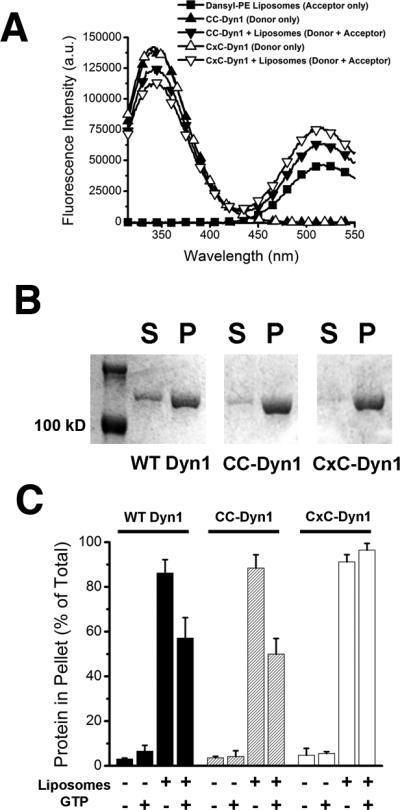
A. Fluorescence emission spectra of 0.1 μM CC-Dyn1 or CxC-Dyn1 (donor) as well as Dansyl-PE (acceptor)-containing liposomes (5 μM total lipid; 90 mol% PS, 10 mol% Dansyl-PE) upon excitation at 280 nm. FRET between the PH domain Trps and Dansyl is evident in the donor+acceptor samples as decrease in donor and increase in acceptor emission. B. Self-assembly of the indicated proteins (1 μM) on liposomes identical to those used in the GTPase assay (300 μM total lipid, Fig. 3F) examined by sedimentation followed by SDS–PAGE analysis of the supernatant (S) and pellet (P) fractions. C. Percentages of proteins pelleted following incubation with or without 400 nm PS liposomes (1 μM protein, 300 μM total lipid) and 1 mM GTP, as indicated, was quantified by sedimentation followed by SDS-PAGE and densitometric analyses of the protein levels in supernatant and pellet fractions (Data shown are average ± Std/ Dev. n=3).
Extended Data Figure 6. Coarse-grained approach to modeling localized membrane constriction by CxC-Dyn1.
A. Schematic representation of the geometry of the ring system used to produce local constriction of a prototype membrane tube. Two pairs of rings are shown, each formed by two closely juxtaposed rings (separated by a small distance Δx). The inner ring in each pair has the radius r and the outer ring has a slightly larger radius r+Δr so that the ring pair promotes creation of an hour-glass membrane shape. The PHDs of dynamin are represented as amphiphilic disks evenly distributed over the rings with the center of mass of each disk being restrained to a position on the ring (marked by blue and orange points). Two overlapping disks (purple and brown) attached to the right juxtaposed ring pair are shown. The orientations of the disks are not fixed so the normal to the disk surface (purple and brown arrows) can have an arbitrary direction. B. Axial cross-section of a stable hemi-fission intermediate, the cylindrical micelle, created by the ring system showed in A. The rectangular box indicates the dimensions of the cylindrical micelles (the diameter D and the length L).
Extended Data Figure 7. Molecular simulations of the hemi-fission and fission transformations.
The red box shows a representative sequence of simulation snapshots (axial cross-sections) demonstrating the formation of the stable hemi-fission intermediate26. Radial constriction of a membrane tube resulted in reversible closure of the tube lumen, i.e. flicker26 followed by formation of a stable cylindrical micelle structure. The blue box summarizes the simulation runs exploring the stability of the hemi-fission intermediate and its rupture. The upper part shows stable structures corresponding to the constrained intermediate (left, taken at zero tension) and the unconstrained intermediate (right, taken at 0.06 Dyn/cm tension). The lower part shows the rupture of the intermediates by 0.6 Dyn/cm tension (left and right) or by elongation of the ring system at 0.06 Dyn/cm tension (middle). The characteristic times for the rupture are indicated near the corresponding blue arrows.
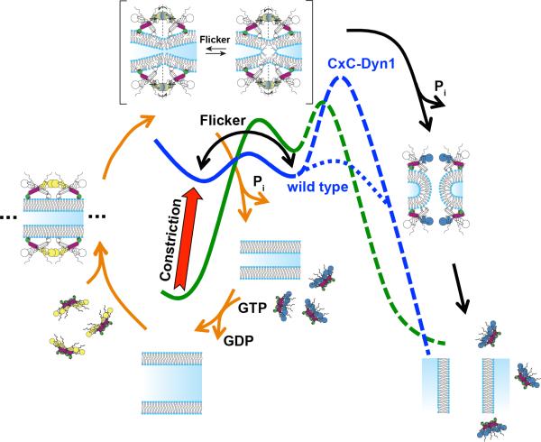
Extended Data Figure 8. Dynamin-catalyzed membrane fission occurs in two mechanistically distinct stages through a hemi-fission intermediate.
Model overlaying the distinct dynamin activities and conformational changes onto the two energy barriers (green curve) that must be overcome, first to catalyze formation of the metastable hemi-fission intermediate and subsequently to drive full fission. When trapped in the transition-state and in the absence of GTP, CxC-Dyn1 can drive the formation of a metastable and flickering hemi-fission state (solid blue curve) through the assembly of small scaffolds and enhanced wedging activity of the PHD. However, without subsequent GTPase driven conformational changes required to loosen the scaffold, generate axial force and retract the PHD, as occurs for WT-Dyn1 (dotted blue line), the membrane-bound CxC-Dyn1 creates an insurmountable barrier to fission (dashed blue line).
Acknowledgements
We thank Josh Chappie for helpful discussions, Aparna Mohanakrishnan and Dana (Kim) Reed for technical assistance. SS was supported by NIH grant R01-GM42455 and the Welch Foundation Grant I-1823. VF was supported by grants from the Spanish Ministry of Economy and Competitiveness BFU2012-34885, the Basque Government Program Etortek, IE12-332 and European FEDER funds. JH was supported by the National Institute of Diabetes and Digestive and Kidney Diseases Intramural Research Program. MF and MM were supported by the Volkswagen foundation and the DFG-CRC803 “Functionality controlled by organization in and between membranes” (B03). J-PM was supported by a postdoctoral research grant from the Academy of Finland.
Footnotes
Author Contributions:
JPM and SLS initiated the project. JPM designed and generated the CC- and CXC-Dyn1 mutants and performed all of the FRET and PET analysis, as well as their biochemical and functional characterization on liposomes and SUPER templates. AVS, ERH and VAF performed the nanotube conductance and GUV experiments. SN characterized the P294 mutants. ACS and JEH performed the cryoEM and negative-stain EM analyses. MF and MM performed the molecular simulations. All authors discussed and interpreted the experimental data and the results of molecular simulation. SLS and VAF coordinated the project and wrote the manuscript, with significant contributions from all co-authors who also approved the final version.
REFERENCES
- 1.Chernomordik LV, Kozlov MM. Mechanics of membrane fusion. Nat Struct Mol Biol. 2008;15:675–683. doi: 10.1038/nsmb.1455. [DOI] [PMC free article] [PubMed] [Google Scholar]
- 2.Kozlov MM, McMahon HT, Chernomordik LV. Protein-driven membrane stresses in fusion and fission. Trends Biochem Sci. 2010;35:699–706. doi: 10.1016/j.tibs.2010.06.003. [DOI] [PMC free article] [PubMed] [Google Scholar]
- 3.Frolov VA, Zimmerberg J. Cooperative elastic stresses, the hydrophobic effect, and lipid tilt in membrane remodeling. FEBS Lett. 2010;584:1824–1829. doi: 10.1016/j.febslet.2010.01.039. [DOI] [PMC free article] [PubMed] [Google Scholar]
- 4.Schmid SL, Frolov VA. Dynamin: functional design of a membrane fission catalyst. Annu Rev Cell Dev Biol. 2011;27:79–105. doi: 10.1146/annurev-cellbio-100109-104016. [DOI] [PubMed] [Google Scholar]
- 5.Ferguson SM, De Camilli P. Dynamin, a membrane-remodelling GTPase. Nat Rev Mol Cell Biol. 2012;13:75–88. doi: 10.1038/nrm3266. [DOI] [PMC free article] [PubMed] [Google Scholar]
- 6.Morlot S, Roux A. Mechanics of dynamin-mediated membrane fission. Annu Rev Biophys. 2013;42:629–649. doi: 10.1146/annurev-biophys-050511-102247. [DOI] [PMC free article] [PubMed] [Google Scholar]
- 7.Cohen FS, Melikyan GB. The energetics of membrane fusion from binding, through hemifusion, pore formation, and pore enlargement. J Membr Biol. 2004;199:1–14. doi: 10.1007/s00232-004-0669-8. [DOI] [PubMed] [Google Scholar]
- 8.Lee JY, Schick M. Calculation of free energy barriers to the fusion of small vesicles. Biophys J. 2008;94:1699–1706. doi: 10.1529/biophysj.107.119511. [DOI] [PMC free article] [PubMed] [Google Scholar]
- 9.Kozlovsky Y, Kozlov MM. Membrane fission: model for intermediate structures. Biophys J. 2003;85:85–96. doi: 10.1016/S0006-3495(03)74457-9. [DOI] [PMC free article] [PubMed] [Google Scholar]
- 10.Frolov VA, Escalada A, Akimov SA, Shnyrova AV. Geometry of membrane fission. Chem Phys Lipids. 2015;185:129–140. doi: 10.1016/j.chemphyslip.2014.07.006. [DOI] [PubMed] [Google Scholar]
- 11.Chappie JS, Acharya S, Leonard M, Schmid SL, Dyda FG. Domain dimerization controls dynamin's assembly-stimulated GTPase activity. Nature. 2010;465:435–440. doi: 10.1038/nature09032. [DOI] [PMC free article] [PubMed] [Google Scholar]
- 12.Chappie JS, et al. A pseudoatomic model of the dynamin polymer identifies a hydrolysis-dependent powerstroke. Cell. 2011;147:209–222. doi: 10.1016/j.cell.2011.09.003. [DOI] [PMC free article] [PubMed] [Google Scholar]
- 13.Gennerich A, Vale RD. Walking the walk: how kinesin and dynein coordinate their steps. Curr Opin Cell Biol. 2009;21:59–67. doi: 10.1016/j.ceb.2008.12.002. [DOI] [PMC free article] [PubMed] [Google Scholar]
- 14.Ramachandran R, Schmid SL. Real-time detection reveals that effectors couple dynamin's GTP-dependent conformational changes to the membrane. EMBO J. 2008;27:27–37. doi: 10.1038/sj.emboj.7601961. [DOI] [PMC free article] [PubMed] [Google Scholar]
- 15.Doose S, Neuweiler H, Sauer M. Fluorescence quenching by photoinduced electron transfer: a reporter for conformational dynamics of macromolecules. Chem Phys Chem. 2009;10:1389–1398. doi: 10.1002/cphc.200900238. [DOI] [PubMed] [Google Scholar]
- 16.Mansoor SE, Dewitt MA, Farrens DL. Distance mapping in proteins using fluorescence spectroscopy: the tryptophan-induced quenching (TrIQ) method. Biochemistry. 2010;49:9722–9731. doi: 10.1021/bi100907m. [DOI] [PMC free article] [PubMed] [Google Scholar]
- 17.Faelber K, et al. Crystal structure of nucleotide-free dynamin. Nature. 2011;477:556–560. doi: 10.1038/nature10369. [DOI] [PubMed] [Google Scholar]
- 18.Ford MG, Jenni S, Nunnari J. The crystal structure of dynamin. Nature. 2011;477:561–566. doi: 10.1038/nature10441. [DOI] [PMC free article] [PubMed] [Google Scholar]
- 19.Pucadyil TJ, Schmid SL. Real-time visualization of dynamin-catalyzed membrane fission and vesicle release. Cell. 2008;135:1263–1275. doi: 10.1016/j.cell.2008.11.020. [DOI] [PMC free article] [PubMed] [Google Scholar]
- 20.Bashkirov PV, et al. GTPase cycle of dynamin is coupled to membrane squeeze and release, leading to spontaneous fission. Cell. 2008;135:1276–1286. doi: 10.1016/j.cell.2008.11.028. [DOI] [PMC free article] [PubMed] [Google Scholar]
- 21.Shnyrova AV, et al. Geometric catalysis of membrane fission driven by flexible dynamin rings. Science. 2013;339:1433–1436. doi: 10.1126/science.1233920. [DOI] [PMC free article] [PubMed] [Google Scholar]
- 22.Sundborger AC, et al. A dynamin mutant defines a superconstricted prefission state. Cell Rep. 2014;8:734–742. doi: 10.1016/j.celrep.2014.06.054. [DOI] [PMC free article] [PubMed] [Google Scholar]
- 23.Mehrotra N, Nichols J, Ramachandran R. Alternate pleckstrin homology domain orientations regulate dynamin-catalyzed membrane fission. Mol Biol Cell. 2014;25:879–890. doi: 10.1091/mbc.E13-09-0548. [DOI] [PMC free article] [PubMed] [Google Scholar]
- 24.Grafmüller A, Shillcock J, Lipowsky R. Pathway of membrane fusion with two tension-dependent energy barriers. Phys Rev Lett. 2007;98:218101. doi: 10.1103/PhysRevLett.98.218101. [DOI] [PubMed] [Google Scholar]
- 25.Risselada HJ, Bubnis G, Grubmüller H. Expansion of the fusion stalk and its implication for biological membrane fusion. Proc Natl Acad Sci USA. 2014;111:11043–11048. doi: 10.1073/pnas.1323221111. [DOI] [PMC free article] [PubMed] [Google Scholar]
- 26.Fuhrmans M, Müller M. Coarse-grained simulation of dynamin-mediated fission. Soft Matter. 2015;11:1464–1480. doi: 10.1039/c4sm02533d. [DOI] [PubMed] [Google Scholar]
- 27.Morlot S, et al. Membrane shape at the edge of the dynamin helix sets location and duration of the fission reaction. Cell. 2012;151:619–629. doi: 10.1016/j.cell.2012.09.017. [DOI] [PMC free article] [PubMed] [Google Scholar]
- 28.Stowell MH, Marks B, Wigge P, McMahon HT. Nucleotide-dependent conformational changes in dynamin: evidence for a mechanochemical molecular spring. Nat Cell Biol. 1999;1:27–32. doi: 10.1038/8997. [DOI] [PubMed] [Google Scholar]
- 29.Loo TW, Clarke DM. Determining the dimensions of the drug-binding domain of human P-glycoprotein using thiol cross-linking compounds as molecular rulers. J Biol Chem. 2001;276:36877–36880. doi: 10.1074/jbc.C100467200. [DOI] [PubMed] [Google Scholar]
- 30.Leonard M, Song BD, Ramachandran R, Schmid SL. Robust colorimetric assays for dynamin's basal and stimulated GTPase activities. Methods Enzymol. 2005;404:490–503. doi: 10.1016/S0076-6879(05)04043-7. [DOI] [PubMed] [Google Scholar]
- 31.Neumann S, Pucadyil TJ, Schmid SL. Analyzing membrane remodeling and fission using supported bilayers with excess membrane reservoir. Nat Protoc. 2013;8:213–222. doi: 10.1038/nprot.2012.152. [DOI] [PMC free article] [PubMed] [Google Scholar]
- 32.Edelstein A, Amodaj N, Hoover K, Vale R, Stuurman N. Computer control of microscopes using microManager. Curr Protoc Mol Biol. 2010 doi: 10.1002/0471142727.mb1420s92. Chapter 14, Unit14.20. [DOI] [PMC free article] [PubMed] [Google Scholar]
- 33.Hömberg M, Müller M. Main phase transition in lipid bilayers: Phase coexistence and line tension in a soft, solvent-free, coarse-grained model. J Chem Phys. 2010;132:155104. doi: 10.1063/1.3369005. [DOI] [PubMed] [Google Scholar]
- 34.Fuhrmans M, Müller M. Mechanisms of vesicle spreading on surfaces: coarse-grained simulations. Langmuir. 2013;29:4335–4349. doi: 10.1021/la400119e. [DOI] [PubMed] [Google Scholar]
- 35.Español P, Warren P. Statistical mechanics of dissipative particle dynamics. EPL. 1995;30:191. [Google Scholar]
- 36.Trofimov SY, Nies EL, Michels MA. Constant-pressure simulations with dissipative particle dynamics. J Chem Phys. 2005;123:144102. doi: 10.1063/1.2052667. [DOI] [PubMed] [Google Scholar]
- 37.Daoulas KC, Müller M. Comparison of simulations of lipid membranes with membranes of block copolymers. Adv Polym Sci. 2010;224:197–233. [Google Scholar]
- 38.Hömberg M, Müller M. The role of inertia and coarse-graining on the transverse modes of lipid bilayers. EPL. 2012;97:68010. [Google Scholar]
