Realization of Logic Gate Using Universal gates (original) (raw)
Last Updated : 23 Jul, 2025
In Boolean Algebra, the **NAND and **NOR gates are called **universal gates because any digital circuit can be implemented by using any one of these two i.e. any logic gate can be created using NAND or NOR gates only.
Implementation of AND Gate using Universal Gates
Implementation using NAND Gates
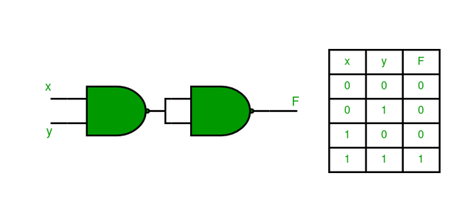
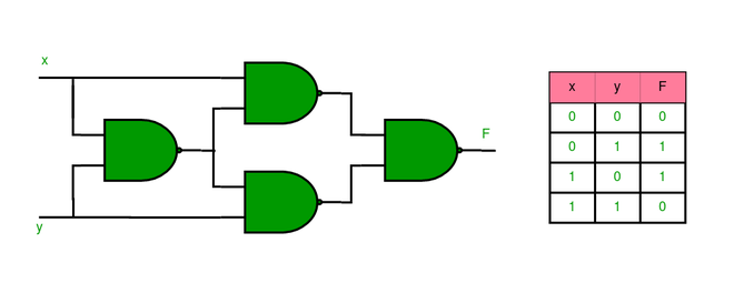
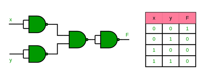
The AND gate is implemented using two NAND gates where the output is HIGH only when both inputs are HIGH. The first NAND gate performs a standard NAND functions, the second NAND gate has both inputs tied to the output of the initial NAND gate as shown below. This particular configuration flips the output thus emulating the behavior of an AND gate.
The AND gate can be implemented by using two NAND gates in the below fashion:
Implementation using NOR Gates
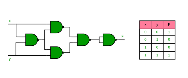
AND gate is implemented using three NOR gates and the setting of this Gate is referred to as 111. The inputs are then transformed with the use of a NOR gate and then they are negated one more time by using two more NOR gates. Together, these create the AND function, meaning that all of the conditions set have to be met in order to pass.
Implementation of AND gate using only NOR gates as shown below
Implementation of OR Gate using Universal Gates
Implementation Using NAND Gates
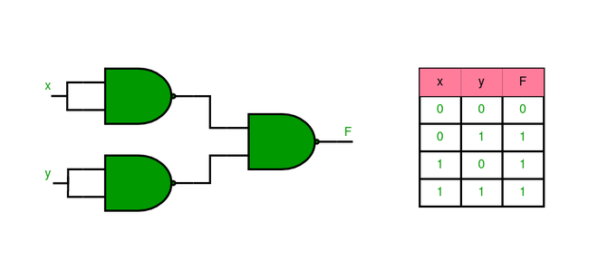
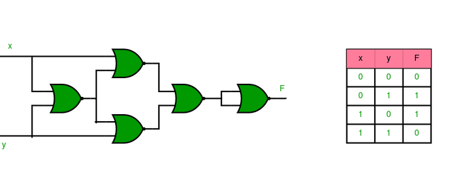
It is implemented using three NAND gates. The inputs are first inverted using two NAND gates having their inputs probed in parallel and then the inverted outputs are connected with the input of third NAND gate. The last NAND gate effectively performs the inverted signals to give the required OR gate function.
The OR gate can be implemented using the NAND gate as below
Implementation using NOR Gates
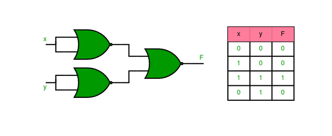
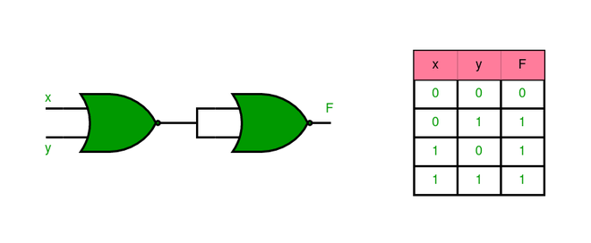
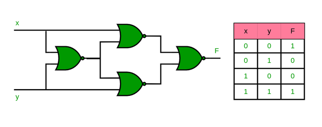
The OR gate is created by using an inverse of the output of the NOR operation. An inverted form of the inputs is provided directly into the NOR gate while the output is provided in NOR gate using fixed inputs. This inversion gives the OR gate logic as shown below.
Implementation of OR gate using two NOR gates as shown in the picture below:
Implementation of NOT Gate using Universal gates.
Implementation using NAND Gates
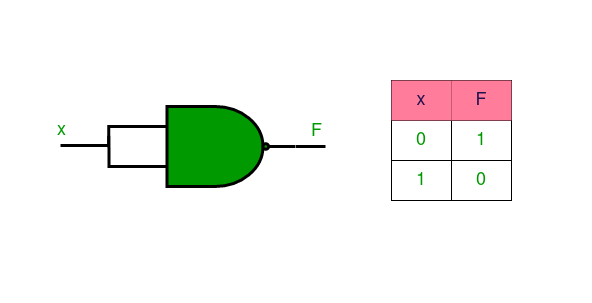
A single NAND gate with ‘a’ and ‘b’ inputs connected respond to a NOT gate. The NOT gate function is achieved as the result of NAND operation because the input signal is inverted.
Implementation of NOT gate using a single NAND gate as shown in the picture below:
Implementation Using NOR Gates
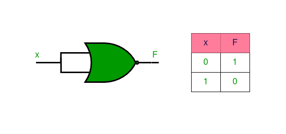
A single NOR gate with joining of both inputs perform the function of NOT gate. The input is negated and the output thus obtained is the inversion that is characteristic of an NOT gate.
Implementation of NOT gate using a single NOR gate as shown in the picture below:
Implementation of XOR Gate using Universal gates.
Implementation using NAND Gates
XOR gate can be implemented using four NAND gates as illustrated below. The circuit first detects differences between inputs and processes them to produce the XOR function.
Implementation of XOR gate using four NAND gate as shown in the picture below
Implementation Using NOR Gates
The XOR gate is implemented by five gates and these gates are the NOR gates. The inputs are then passed through a number of NOR gates to remove all the non-exclusive conditions before the XOR is applied to them.
Implementation of XOR gate using five NOR gate as shown in the picture below:
Implementation of XNOR Gate using Universal Gates
Implementation Using NAND Gate
XNOR gate is implemented by five NAND gates to make the circuit. The XOR logic is first obtained, and then the outgoing XOR signal is passed through a NAND gate that negates it to obtain the XNOR function.
Implementation of XNOR gate using five NAND gate as shown in the picture below:
Implementation Using NOR Gate
The XNOR gate can be implemented using four NOR gates. The XOR logic is then allowed to pass through a NOR gate, and the logic of output obtained will be the XNOR.
Implementation of XNOR gate using four NOR gate as shown in the picture below:
Implementation of NOR Gate using NAND Gates
NOR gate is formed by using four NAND gates. The first two gates perform the operation of inversion of inputs while the subsequent two gates perform the normal NOR operation.
Implementation of NOR gate using four NAND gate as shown in the picture below:
Implementation of NAND Gate using NOR Gates
The NAND gate is made using four NOR gates. The first two gates invert the inputs, and next two gates perform the operations equivalent to NAND operation by these inverted signals.
Implementation of NAND gate using four NOR gate as shown in the picture below

Advantages of Using Universal Gates
- **Simplicity: These are gates that can be used for all forms of logical operations hence can help reduce the number of components in a circuit.
- **Cost-Effective: Fewer parts are required when developing one type of gate only thus lowering costs of manufacturing.
- **Flexibility:Universal gates can perform any digital logic function which makes it convenient to design any type of circuit.
- **Reliability: The dependence of a small number of various gates can result in increased reliability in digital circuits.
- **Ease of Integration: Universal gates can be easily integrated into existing systems, even for complex designs.
Disadvantages of Using Universal Gates
- **Increased Gate Count: Complex logic functions are more difficult to construct using only NAND or NOR gates in that they take up more gates than other basic gates.
- **Higher Power Consumption: Additional gates increase power consumption, especially in complex circuits.
- **Slower Speed: Extra gates can also bring in more propagation delay, and hence lower the speed of the circuit.
- **Complex Design: The circuit design becomes more complicated because of a high number of universal gates the functions contain.
- **Limited Optimization: The use of only one type of gate may offer fewer optimization possibilities and therefore result in less efficient designs.
Applications of Universal Gates
- **Basic Digital Circuits: Universal gates are employed widely in elementary digital circuits for carrying out simple logical operations.
- **Memory Units: NAND and NOR gates are used in memory storage elements such as SRAM and DRAM among others in the manufacture of devices that are used in the modern world.
- **Arithmetic Logic Units (ALUs): The universal gates are used in ALUs to transform constant and variable, arithmetic and logical operations with the aid of processors.
- **Signal Processing: In filter design and other communication processing systems popularly known as modulation techniques, universal gates are employed.
- **Embedded Systems: Universal gates play a significant role in the construction of small scale circuits to be used in the embedded systems applications.