CIC Interpolation - Interpolate signal using cascaded integrator-comb filter - Simulink (original) (raw)
Interpolate signal using cascaded integrator-comb filter
Libraries:
DSP System Toolbox / Filtering / Multirate Filters
DSP System Toolbox HDL Support / Filtering
Description
The CIC Interpolation block performs a sample rate increase (interpolation) on an input signal by an integer factor. Cascaded integrator-comb (CIC) filters are a class of linear phase FIR filters that consist of a comb part and an integrator part.
The CIC Interpolation block requires a Fixed-Point Designer™ license.
Ports
Input
Specify the data input as a vector or a matrix.
If the input is fixed point, it must be a signed integer or a signed fixed point value with a power-of-two slope and zero bias.
Data Types: int8 | int16 | int32 | int64 | fixed point
Complex Number Support: Yes
Output
CIC interpolated output, returned as a vector or a matrix. The data type of the output is determined by the settings in the block dialog. The complexity of the output matches that of the input. The number of output rows is_R_✕Num, where R is the interpolation factor and Num is the number of input rows.
Data Types: int8 | int16 | int32 | int64 | fixed point
Complex Number Support: Yes
Parameters
Source of the filter information, specified as one of the following:
Dialog parameters— Enter information about the filter, such as Interpolation factor (R),Differential delay (M) and Number of sections (N), in the block dialog.Filter object— Specify the filter using adsp.CICInterpolator System object™.
Interpolation factor of the filter, specified as an integer greater than 1.
Dependencies
This parameter appears when you set Coefficient source toDialog parameters.
Specify the differential delay of the comb part of the filter, M, as a positive integer. For more details, see CIC Interpolation Filter.
Dependencies
This parameter appears when you set Coefficient source toDialog parameters.
Specify the number of filter sections. The number you specify determines the number of sections in either the comb part of the filter or the integrator part of the filter. This value does not represent the total number of sections in the comb and integrator parts combined.
Dependencies
This parameter appears when you set Coefficient source toDialog parameters.
Choose how you specify the fixed-point word length and fraction length of the filter sections and/or output:
Full precision— The word and fraction lengths of the filter sections and outputs are automatically selected for you. The output and last section word lengths (WL) are set to:
where,- I –– Input word length
- M –– Differential delay
- N –– Number of sections
- R –– Interpolation factor
The other section word lengths are set to accommodate the bit growth, as described in Hogenauer's paper [1]. All fraction lengths are set to the input fraction length.
Minimum section word lengths— Specify the word length of the filter output in the Output word length parameter. The word lengths of the filter sections are set in the same way as inFull precisionmode.
The section fraction lengths are set to the input fraction length. The output fraction length is set to the input fraction length minus the difference between the last section word length and the output word length.Specify word lengths— Specify the word lengths of the filter sections and output in the Section word lengths and Output word length parameters. The fraction lengths of the filter sections are set such that the spread between word length and fraction length is the same as in full-precision mode. The output fraction length is set to the input fraction length minus the difference between the last section word length and the output word length.Binary point scaling— Specify the word and fraction lengths of the filter sections and output in the Section word lengths, Section fraction lengths,Output word length, and Output fraction length parameters.
Dependencies
This parameter appears when you set Coefficient source toDialog parameters.
Word lengths of filter sections, specified as a scalar or a vector of length equal to 2_N_, where N is the number of filter sections. The section word length must be in the range [2, 128].
Dependencies
This parameter appears when you set Coefficient source toDialog parameters and Data type specification mode to either Specify word lengths orBinary point scaling.
Fraction lengths of filter sections, specified as an integer.
Dependencies
This parameter appears when you set Coefficient source toDialog parameters and Data type specification mode to Binary point scaling.
Word length of the filter output, specified as an integer in the range [2, 128].
Dependencies
This parameter appears when you set Coefficient source toDialog parameters and Data type specification mode to any option other than Full precision.
Fraction length of the filter output, specified as an integer.
Dependencies
This parameter appears when you set Coefficient source toDialog parameters and Data type specification mode to Binary point scaling.
Specify how the block should process the input. You can set this parameter to one of the following options:
Columns as channels (frame based)— The block treats each column of the input as a separate channel. In this mode, the block always performs single-rate processing.Elements as channels (sample based)— The block treats each element of the input as a separate channel. In this mode, the input to the block must be a scalar or a vector. You can use the Rate options parameter to specify whether the block performs single-rate or multirate processing.
Specify the rate processing rule for the block. You can select one of the following options:
Enforce single-rate processing— The block maintains the sample rate of the input.Allow multirate processing— The block produces an output with a sample rate that is R times faster than the input sample rate. To select this option, you must set the Input processing parameter toElements as channels (sample based).
Specify the name of the multirate filter object that you want the block to implement. You must specify the filter as a dsp.CICInterpolator System object.
You can define the System object in the block dialog or in a MATLAB® workspace variable.
For information on creating System objects, see Define Basic System Objects.
Dependencies
This parameter appears when you set Coefficient source toFilter object.
This button opens the Filter Visualization Tool (FVTool) from the Signal Processing Toolbox™ product and displays the filter response of the filter defined in the block. For more information on FVTool, see the Signal Processing Toolbox documentation.
Note
If you specify a filter in the Filter object parameter, you must apply the filter by clicking the Apply button before using the View Filter Response button.
Block Characteristics
| Data Types | fixed point | integer |
|---|---|
| Direct Feedthrough | no |
| Multidimensional Signals | no |
| Variable-Size Signals | no |
| Zero-Crossing Detection | no |
More About
CIC filters are an optimized class of linear phase FIR filters composed of a comb part and an integrator part.
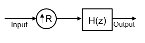
The CIC interpolation filter is conceptually given by an upsampler followed by a single rate CIC filter, H(z), which is a lowpass anti-imaging filter. The CIC interpolation filter increases the sample rate of an input signal by an integer factor using a cascaded integrator-comb (CIC) filter.
In a more efficient implementation, the single rate CIC filter H(z) is factorized this way:
where,
- _H_C is the transfer function of the N sections of the cascaded comb filters, each with a width of RM.
- _H_I is the transfer function of the integrator part of the filter containing N stages of integrators.
- N is the number of sections. The number of sections in a CIC filter is defined as the number of sections in either the comb part or the integrator part of the filter. This value does not represent the total number of sections throughout the entire filter.
- R is the interpolation factor.
- M is the differential delay.
In the overall multirate realization, the algorithm applies the noble identity for interpolation and moves the rate change factor, R, to follow after the N sections of the cascaded comb filters.
The transfer function of the resulting filter is given by the following equation:
For a block diagram that shows the multirate implementation, see Algorithms.
Algorithms
The CIC interpolation filter in More About is realized as a cascade of N sections of comb filters followed by a rate change by a factor R, followed by N sections of cascaded integrators.
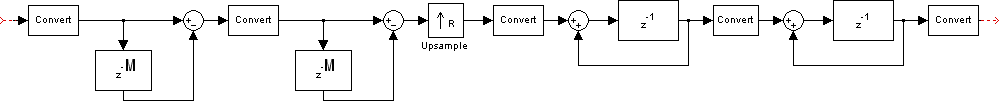
This diagram shows two sections of cascaded comb filters and two sections of cascaded integrators. The unit delay in the integrator portion of the CIC filter can be located in either the feedforward or the feedback path. These two configurations yield identical filter frequency response. However, the numerical outputs from these two configurations are different due to the latency. This algorithm puts the unit delay in the feedforward path of the integrator since it is a preferred configuration for HDL implementation.
References
[1] Hogenauer, E.B. “An Economical Class of Digital Filters for Decimation and Interpolation” IEEE Transactions on Acoustics, Speech and Signal Processing. Vol. 29, Number 2, 1981, pp. 155–162, 1981.
[2] Meyer-Baese, U. Digital Signal Processing with Field Programmable Gate Arrays. New York: Springer Verlag, 2001.
[3] Harris, Fredric J., Multirate Signal Processing for Communication Systems. Upper Saddle River, NJ: Prentice Hall PTR, 2004.
Extended Capabilities
Generated code relies on the memcpy ormemset function (string.h) under certain conditions.
HDL Coder™ provides additional configuration options that affect HDL implementation and synthesized logic.
Note
For an HDL-optimized filter architecture with hardware-friendly control signals, use the CIC Interpolator (DSP HDL Toolbox) block. The DSP HDL Toolbox™ block simulates the latency of the HDL algorithm in Simulink®.
HDL Architecture
The block has HDLDataPath as a default architecture. This architecture provides additional configuration options that affect HDL implementation and synthesized logic.
HDL Block Properties
| HDL Block Properties | Description |
|---|---|
| InputPipeline | Number of input pipeline stages to insert in the generated code. Distributed pipelining and constrained output pipelining can move these registers. The default is 0. For more details, see InputPipeline (HDL Coder). |
| OutputPipeline | Number of output pipeline stages to insert in the generated code. Distributed pipelining and constrained output pipelining can move these registers. The default is 0. For more details, see OutputPipeline (HDL Coder). |
| ConstrainedOutputPipeline | Number of registers to place at the outputs by moving existing delays within your design. Distributed pipelining does not redistribute these registers. The default is 0. For more details, see ConstrainedOutputPipeline (HDL Coder). |
| AddPipelineRegisters | Insert a pipeline register between stages of computation in a filter. See also AddPipelineRegisters (HDL Coder). |
Data Type Support
The block supports these data types for HDL code generation:
| Input Port | Dimension | Fixed-Point | Floating-Point | Built-in Integers | Bus | Boolean | Enumerated | Complex Signal |
|---|---|---|---|---|---|---|---|---|
| Port_1 | Scalar | Yes | HalfSingleDouble | Yes | No | Yes | Yes | Yes |
Block Parameter Configuration
These block parameter configurations are incompatible with HDL code generation.
| Block Parameter | Limitations |
|---|---|
| Rate options | Parameter value Enforce single-rate processing is not supported. |
| Input processing | Parameter value Columns as channels (frame based) is not supported. |
Optimizations
The block participates in these HDL optimizations to optimize the speed, and area.
Area Optimization
| Optimization | Description |
|---|---|
| Resource Sharing (HDL Coder) | Resource sharing is an area optimization in which HDL Coder identifies multiple functionally equivalent resources and replaces them with a single resource. |
| Streaming (HDL Coder) | Streaming is an area optimization in which HDL Coder transforms a vector data path to a scalar data path (or to several smaller-sized vector data paths). |
Speed Optimization
| Optimization | Description |
|---|---|
| Distributed Pipelining (HDL Coder) | Distributed pipelining, or register retiming, is a speed optimization that moves existing delays in a design to reduce the critical path while preserving functional behavior. |
| Clock-Rate Pipelining (HDL Coder) | Clock-rate pipelining is an optimization framework in HDL Coder that allows other speed and area optimizations to introduce latency at the clock rate. |
| Adaptive Pipelining (HDL Coder) | Adaptive pipelining optimization creates patterns or combination of blocks with registers that can improve the achievable clock frequency and reduce the area usage on the FPGA boards by inserting pipeline registers to the blocks in your design. |
| Critical Path Estimation (HDL Coder) | To quickly identify the most likely critical path in your design, use_Critical Path Estimation_. Critical path estimation speeds up the iterative process of finding the critical path. To know blocks that are characterized in critical path estimation, see Characterized Blocks (HDL Coder). |
Limitations and Considerations
- Vector and frame inputs are not supported for HDL code generation.
When you use AddPipelineRegisters, registers are placed based on the filter structure. The pipeline register placement determines the latency.
| Pipeline Register Placement | Latency (clock cycles) |
|---|---|
| A pipeline register is added between the comb stages of the differentiators. | NS-1, where NS is number of sections (at the output side). |
Version History
Introduced before R2006a
See Also
Functions
Objects
- dsp.CICDecimator | dsp.CICInterpolator | dsp.FIRDecimator | dsp.FIRInterpolator | dsp.CICCompensationDecimator | dsp.CICCompensationInterpolator | dsp.FIRHalfbandDecimator | dsp.FIRHalfbandInterpolator