FIR Interpolation - Perform polyphase FIR interpolation - Simulink (original) (raw)
Perform polyphase FIR interpolation
Libraries:
DSP System Toolbox / Filtering / Multirate Filters
DSP System Toolbox HDL Support / Filtering
Description
The FIR Interpolation block performs an efficient polyphase interpolation using an integer upsampling factor L along the first dimension.
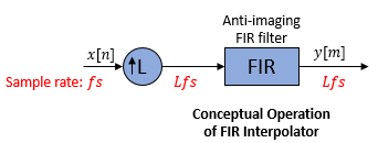
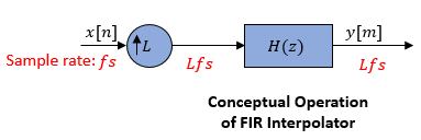
Conceptually, the FIR interpolator (as shown in the schematic) consists of an upsampler followed by an FIR anti-imaging filter, which is usually an approximation of an ideal band-limited interpolation filter. To design an FIR anti-imaging filter, use the designMultirateFIR function. The upsampler upsamples each channel of the input to a higher rate by inserting _L_–1 zeros between samples. The FIR filter that follows filters each channel of the upsampled data. The resulting discrete-time signal has a sample rate that is L times the original sample rate.
However, the actual block algorithm implements a direct-form FIR polyphase structure, an efficient equivalent of the combined system depicted in the diagram. For more details, see Algorithms.
You can use the FIR Interpolation block inside triggered subsystems when you set theRate options parameter to Enforce single-rate processing.
Under specific conditions, this block also supports SIMD code generation. For more details, see Code Generation.
Examples
Ports
Input
Specify the data input as a vector or a matrix.
When you set Input processing toColumns as channels (frame based) andRate options to Enforce single-rate processing, the input can be a variable-size signal. That is, the frame size (number of rows) and the number of channels (columns) of the signal can change during simulation.
This port is unnamed until you set Coefficient source to Input port.
Data Types: single | double | int8 | int16 | int32 | uint8 | uint16 | uint32 | fixed point
Complex Number Support: Yes
Specify the numerator coefficients of the FIR filter as a vector.
The transfer function H(z) of the FIR filter is given by:
You can generate the FIR filter coefficient vector, b = [b0,b1, …,_bN_], using one of the DSP System Toolbox™ filter design functions such as designMultirateFIR,firnyquist, firgr or firceqrip.
To act as an effective anti-imaging filter, the coefficients usually correspond to a lowpass filter with a normalized cutoff frequency no greater than the reciprocal of the interpolation factor. To design such a filter, use the designMultirateFIR function.
Coefficient values are tunable. That is, their values can change during simulation while their properties such as size, data type, and complexity cannot change.
The data type of the Num input must match the data type of the In input.
Dependencies
The Num input port appears when you setCoefficient source as Input port.
Data Types: single | double | int8 | int16 | int32 | uint8 | uint16 | uint32 | fixed point
Complex Number Support: Yes
Output
Output of the FIR Interpolator block, returned as a vector or a matrix.
When Rate options is set to:
Enforce single-rate processing— When you select this option, the block maintains the input sample rate, and interpolates the signal by increasing the output frame size by a factor of L.Allow multirate processing— When you select this option, the block interpolates the signal such that the output sample rate is L times faster than the input sample rate.
When the input is a variable-size signal, the output is also a variable-size signal.
This port is unnamed until you set Coefficient source to Input port.
Data Types: single | double | int8 | int16 | int32 | uint8 | uint16 | uint32 | fixed point
Complex Number Support: Yes
Parameters
Coefficient source
Specify the FIR filter coefficient source as one of the following:
- Dialog parameters –– Specify the filter coefficients through the FIR filter coefficients parameter in the block dialog box.
- Input port –– Specify the filter coefficients through the Num input port.
- Filter object –– Specify the filter using a dsp.FIRInterpolator System object™.
- Auto –– When you selectAuto, the block designs an FIR interpolator using the interpolation factor you specify inInterpolation factor. The designMultirateFIR function designs the filter and returns the coefficients used by the block.
For more information on the filter design, see Orfanidis [2].
Main Tab
Specify the numerator coefficients of the FIR filter transfer function_H_(z).
You can generate the FIR filter coefficient vector, b = [b0,b1, …,_bN_], using one of the DSP System Toolbox filter design functions such as designMultirateFIR, firnyquist, firgr or firceqrip.
To act as an effective anti-imaging filter, the coefficients usually correspond to a lowpass filter with a normalized cutoff frequency no greater than the reciprocal of the interpolation factor. To design such a filter, use the designMultirateFIR function.
The block internally initializes all filter states to zero.
Dependencies
This parameter appears only when you set the Coefficient source to Dialog parameters.
Data Types: single | double | int8 | int16 | int32 | int64 | uint8 | uint16 | uint32 | uint64
Complex Number Support: Yes
Specify the integer factor L. The block increases the sample rate of the input sequence by this factor.
Dependencies
This parameter appears only when you set the Coefficient source to Dialog parameters,Input port, orAuto.
Data Types: single | double | int8 | int16 | int32 | int64 | uint8 | uint16 | uint32 | uint64
Specify the name of the multirate filter object that you want the block to implement. You must specify the filter as a dsp.FIRInterpolator System object.
You can define the System object directly in the block dialog box. Alternatively, you can define the object in a MATLAB® workspace variable and specify the variable in the block dialog box.
For information on creating System objects, see Define Basic System Objects.
Dependencies
This parameter appears only when you set the Coefficient source to Filter object.
Specify how the block should process the input. You can set this parameter to one of the following options:
Columns as channels (frame based)— When you select this option, the block treats each column of the input as a separate channel.Elements as channels (sample based)— When you select this option, the block treats each element of the input as a separate channel.
Specify the method by which the block should interpolate the input. You can select one of the following options:
Enforce single-rate processing— When you select this option, the block maintains the input sample rate, and interpolates the signal by increasing the output frame size by a factor of L. To select this option, you must set the Input processing parameter toColumns as channels (frame based).Allow multirate processing— When you select this option, the block interpolates the signal such that the output sample rate is L times faster than the input sample rate.
When you set the Rate options parameter toAllow multirate processing and run your models in Simulink® MultiTasking mode, the block exhibits latency. The amount of latency for multirate, multitasking operation depends on how you set theInput processing parameter.
| Input processing | Latency |
|---|---|
| Elements as channels (sample based) | L samples |
| Columns as channels (frame based) | L frames (Ki samples per frame) |
When the block exhibits latency, the default initial condition is zero. Alternatively, you can use the Output buffer initial conditions parameter to specify a matrix of initial conditions containing one value for each channel or a scalar initial condition that the block applies to all channels. The block divides theOutput buffer initial conditions by theInterpolation factor and outputs the scaled initial conditions until the first filtered input sample becomes available.
Output buffer initial conditions are stored in the output data type and scaling.
See Latency for more information about latency in the FIR Interpolation block.
Dependencies
This parameter appears only when you configure the block to perform multirate processing by setting Rate options toAllow multirate processing.
Data Types: single | double | int8 | int16 | int32 | int64 | uint8 | uint16 | uint32 | uint64
Complex Number Support: Yes
Click on this button to open the Filter Visualization Tool (fvtool) and display the filter response of the filter defined in the block dialog box.
Data Types Tab
Select the rounding mode for fixed-point operations. The default isFloor. The filter coefficients do not obey this parameter and always round toNearest.
Note
The Rounding mode and Saturate on integer overflow settings have no effect on numerical results when all the following conditions exist:
- Product output is
Inherit: Inherit via internal rule - Accumulator is
Inherit: Inherit via internal rule - Output is
Inherit: Same as accumulator
With these data type settings, the block is effectively operating in the full-precision mode.
When you select this parameter, the block saturates the result of its fixed-point operation. When you clear this parameter, the block wraps the result of its fixed-point operation. For details onsaturate and wrap, see overflow mode for fixed-point operations.
Note
The Rounding mode and Saturate on integer overflow parameters have no effect on numeric results when all these conditions are met:
- Product output data type is
Inherit: Inherit via internal rule. - Accumulator data type is
Inherit: Inherit via internal rule.
With these data type settings, the block operates in the full-precision mode.
Specify the coefficients data type. See Fixed-Point Data Types and Multiplication Data Types for illustrations depicting the use of the coefficients data type in this block.
You can set this parameter to one of the following:
Inherit: Same word length as inputfixdt(1,16,0)orfixdt(1,16)–– Specify a data type object.
Click the Show data type assistant button to display the Data Type Assistant, which helps you set theCoefficients parameter.
See Specify Data Types Using Data Type Assistant (Simulink) for more information.
Dependencies
This parameter appears only when you set Coefficient source to Dialog parameters,Filter object, orAuto.
When Coefficient source is set toFilter object,Coefficients parameter is automatically set toSame word length as input.
Specify the minimum value of the filter coefficients. The default value is[] (unspecified). Simulink software uses this value to perform automatic scaling of fixed-point data types.
Dependencies
This parameter appears only when you set Coefficient source to Dialog parameters orAuto.
Specify the maximum value of the filter coefficients. The default value is[] (unspecified). Simulink software uses this value to perform automatic scaling of fixed-point data types.
Dependencies
This parameter appears only when you set Coefficient source to Dialog parameters orAuto.
Specify the product output data type. See Fixed-Point Data Types and Multiplication Data Types for illustrations depicting the use of the product output data type in this block.
You can set this parameter to one of the following:
Inherit: Inherit via internal rule
For more information on this rule, see Inherit via Internal Rule.Inherit: Same as inputfixdt(1,16,0)–– Specify a data type object.
Click the Show data type assistant button to display the Data Type Assistant, which helps you set the Product output parameter.
See Specify Data Types Using Data Type Assistant (Simulink) for more information.
Dependencies
When Coefficient source is set toFilter object, Product output parameter is automatically set to Full precision.
Specify the accumulator data type. See Fixed-Point Data Types for illustrations depicting the use of the accumulator data type in this block.
You can set this parameter to one of the following:
Inherit: Inherit via internal rule.
For more information on this rule, see Inherit via Internal Rule.Inherit: Same as inputInherit: Same as product outputfixdt(1,16,0)–– Specify a data type object.
Click the Show data type assistant button to display the Data Type Assistant, which helps you set theAccumulator parameter.
See Specify Data Types Using Data Type Assistant (Simulink) for more information.
Dependencies
When Coefficient source is set toFilter object,Accumulator parameter is automatically set toFull precision.
Specify the output data type. See Fixed-Point Data Types for illustrations depicting the use of the output data type in this block.
You can set it to one of the following:
Inherit: Same as accumulatorInherit: Same as inputInherit: Same as product outputfixdt(1,16,0)–– Specify a data type object.
Click the Show data type assistant button to display the Data Type Assistant, which helps you set theOutput parameter.
See Control Data Types of Signals (Simulink) for more information.
Dependencies
When Coefficient source is set toFilter object,Output parameter is automatically set toSame as accumulator.
Specify the minimum value that the block should output. The default value is [] (unspecified). Simulink software uses this value to perform:
- Simulation range checking (see Specify Signal Ranges (Simulink))
- Automatic scaling of fixed-point data types
Dependencies
This parameter appears only when you set Coefficient source to Dialog parameters,Input port, orAuto.
Specify the maximum value that the block should output. The default value is [] (unspecified). Simulink software uses this value to perform:
- Simulation range checking (see Specify Signal Ranges (Simulink))
- Automatic scaling of fixed-point data types
Dependencies
This parameter appears only when you set Coefficient source to Dialog parameters,Input port, orAuto.
Block Characteristics
| Data Types | double | fixed point | integer | single |
|---|---|---|---|
| Direct Feedthrough | no | ||
| Multidimensional Signals | no | ||
| Variable-Size Signals | yes | ||
| Zero-Crossing Detection | no |
More About
When you set the Input processing parameter toColumns as channels (frame based), the block resamples each column of the input over time. In this mode, the block can perform either single-rate or multirate processing. You can use the Rate options parameter to specify how the block resamples the input:
- When you set the Rate options parameter to
Enforce single-rate processing, the input and output of the block have the same sample rate. To interpolate the output while maintaining the input sample rate, the block resamples the data in each column of the input such that the frame size of the output (Ko) is_L_ times larger than that of the input (Ko =Ki*L).
For an example of single-rate FIR Interpolation, see FIR Interpolation Using Single-Rate Processing. - When you set the Rate options parameter to
Allow multirate processing, the input and output of the FIR Interpolation block are the same size. However, the sample rate of the output is L times faster than that of the input. In this mode, the block treats a_Ki_-by-N matrix input as N independent channels. The block interpolates each column of the input over time by keeping the frame size constant (_Ki_=Ko), while making the output frame period (Tfo) L times shorter than the input frame period (Tfo =Tfi/L).
See FIR Interpolation Using Multirate Frame-Based Processing for an example that uses the FIR Interpolation block in this mode.
When you set the Input processing parameter toElements as channels (sample based), the block treats a P_-by-Q matrix input as_P*Q independent channels, and interpolates each channel over time. The output sample period (Tso) is L times shorter than the input sample period (Tso =Tsi/L), while the input and output sizes remain identical.
When you run your models in the SimulinkSingleTasking mode or set the Input processing parameter to Columns as channels (frame based) and the Rate options parameter toEnforce single-rate processing, the FIR Interpolation block always has zero-tasking latency. Zero-tasking latency means that the block propagates the first filtered input sample (received at time_t_=0) as the first output sample. That first output sample is then followed by _L_–1 interpolated values, the second filtered input sample, and so on.
The only time the FIR Interpolation block exhibits latency is when you set theRate options parameter set to Allow multirate processing and run your models in the SimulinkMultiTasking mode. The amount of latency for a multirate, multitasking operation depends on how you set the Input processing parameter.
| Input processing | Latency |
|---|---|
| Elements as channels (sample based) | L samples |
| Columns as channels (frame based) | L frames (Ki samples per frame) |
When the block exhibits latency, the default initial condition is zero. Alternatively, you can use the Output buffer initial conditions parameter to specify a matrix of initial conditions containing one value for each channel or a scalar initial condition that the block applies to all channels. The block scales the Output buffer initial conditions by theInterpolation factor and outputs the scaled initial conditions until the first filtered input sample becomes available.
When the block is in the sample-based processing mode, the block outputs the scaled initial conditions at the start of each channel, followed immediately by the first filtered input sample, then _L_–1 interpolated values, and so on.
When the block is in the frame-based processing mode and using the default initial condition of zero, the first_Ki_*L output rows contain zeros, where Ki is the input frame size. The first filtered input sample (first filtered row of the input matrix) appears in the output as sample_Ki_*L+1. That value is then followed by _L_–1 interpolated values, the second filtered input sample, and so on.
The following diagram shows the data types used within the FIR Interpolation block for fixed-point signals.
This diagram shows that input data is stored in the input buffer with the same data type and scaling as the input. The block stores filtered data and any initial conditions in the output buffer using the output data type and scaling that you set in the block dialog box.
When at least one of the inputs to the multiplier is real, the output of the multiplier is in the product output data type. When both inputs to the multiplier are complex, the result of the multiplication is in the accumulator data type. For details on the complex multiplication performed by this block, see Multiplication Data Types.
Note
When the block input is fixed point, all internal data types are signed fixed point.
Algorithms
The FIR interpolation filter is implemented efficiently using a polyphase structure.
To derive the polyphase structure, start with the transfer function of the FIR filter:
N+1 is the length of the FIR filter.
You can rearrange this equation as follows:
L is the number of polyphase components, and its value equals the interpolation factor that you specify.
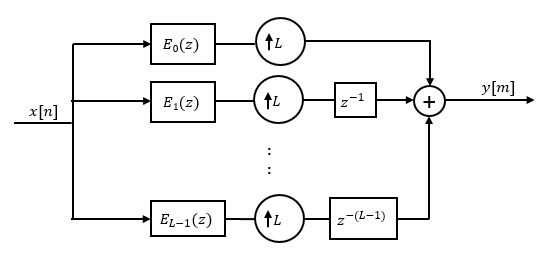
You can write this equation as:
E0(zL),E1(zL), ...,EL-1(zL) are polyphase components of the FIR filter H(z).
Conceptually, the FIR interpolation filter contains an upsampler followed by an FIR lowpass filter H(z).
Replace H(z) with its polyphase representation.
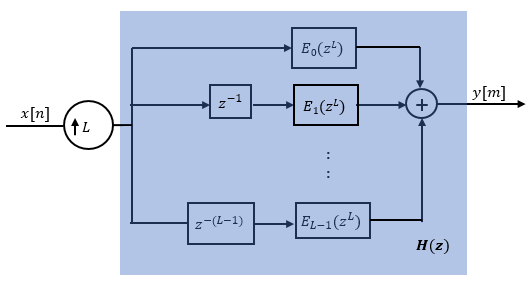
Here is the multirate noble identity for interpolation.
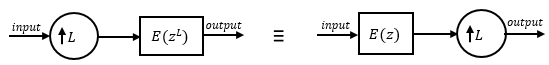
Applying the noble identity for interpolation moves the upsampling operation to after the filtering operation. This move enables you to filter the signal at a lower rate.
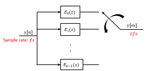
You can replace the upsampling operator, delay block, and adder with a commutator switch. The switch starts on the first branch 0 and moves in the counterclockwise direction, each time receiving one sample from each branch. The interpolator effectively outputs_L_ samples for every one input sample it receives. Hence the sample rate at the output of the FIR interpolation filter is Lfs.
References
[1] Fliege, N. J. Multirate Digital Signal Processing: Multirate Systems, Filter Banks, Wavelets. West Sussex, England: John Wiley & Sons, 1994.
[2] Orfanidis, Sophocles J. Introduction to Signal Processing. Upper Saddle River, NJ: Prentice-Hall, 1996.
Extended Capabilities
Generated code relies on the memcpy ormemset function (string.h) under certain conditions.
Generate SIMD code using Intel® AVX2 code replacement library
Note
Requires Embedded Coder® license
The FIR Interpolation block supports SIMD code generation using Intel AVX2 code replacement library under these conditions:
- Input processing is set to
Columns as channels (frame based). - Rate options is set to
Enforce single-rate processing. - Input signal is real-valued with real filter coefficients.
- Input signal is complex-valued with real or complex filter coefficients.
- Input signal has a data type of
singleordouble.
To generate SIMD code from this block using this workflow, see Use Intel AVX2 Code Replacement Library to Generate SIMD Code from Simulink Blocks.
Generate SIMD code by leveraging target hardware instruction set extensions (since R2023a)
Note
Requires Simulink Coder™ or Embedded Coder license
You can generate SIMD code for the FIR Interpolation block on all Intel platforms, ARM® Cortex®-A processors, and Apple silicon processors by using the model configuration parameterLeverage target hardware instruction set extensions under these conditions:
- You set Input processing to
Columns as channels (frame based) - Input signal is real-valued with real filter coefficients
- Input signal is complex-valued with real or complex filter coefficients.
- Data type of the input signal is
single(ARM Cortex-A processors) - Data type of the input signal is
singleordouble(Intel platforms)
In addition, configure your model appropriately. In theModeling tab of the Simulink model window, click Model Settings and configure these parameters under Code Generation.
- In the Optimization pane:
- Provide a specific instruction set in theLeverage target hardware instruction set extensions parameter.
- Select the Optimize reductions parameter.
- Under Optimization levels, setLevel to
MaximumandPriority toMaximize execution speed.
- In the Interface pane, under Software environment, clear non-finite numbers.
To generate SIMD code from this block using this workflow, see Use Target Hardware Instruction Set Extensions to Generate SIMD Code from Simulink Blocks for Intel Platforms, Use Target Hardware Instruction Set Extensions to Generate SIMD Code from Simulink Blocks for Apple silicon, and Use Target Hardware Instruction Set Extensions to Generate SIMD Code from Simulink Blocks for ARM Cortex-A Processors.
For computationally intensive operations on supported blocks, SIMD intrinsics can significantly improve the performance of the generated code on Intel platforms. For more details, see Optimize Code for Reduction Operations by Using SIMD (Simulink Coder).
For more information on SIMD code generation in DSP System Toolbox, see SIMD Code Generation.
HDL Coder™ provides additional configuration options that affect HDL implementation and synthesized logic.
Note
For an HDL-optimized filter architecture with hardware-friendly control signals that supports vector input and output data, use the FIR Interpolator (DSP HDL Toolbox) block. The DSP HDL Toolbox™ block simulates the latency of the HDL algorithm in Simulink.
HDL Architecture
The block has HDLDataPath as a default architecture. This architecture provides additional configuration options that affect HDL implementation and synthesized logic.
HDL Block Properties
| HDL Block Properties | Description |
|---|---|
| InputPipeline | Number of input pipeline stages to insert in the generated code. Distributed pipelining and constrained output pipelining can move these registers. The default is 0. For more details, see InputPipeline (HDL Coder). |
| OutputPipeline | Number of output pipeline stages to insert in the generated code. Distributed pipelining and constrained output pipelining can move these registers. The default is 0. For more details, see OutputPipeline (HDL Coder). |
| ConstrainedOutputPipeline | Number of registers to place at the outputs by moving existing delays within your design. Distributed pipelining does not redistribute these registers. The default is 0. For more details, seeConstrainedOutputPipeline (HDL Coder). |
| FlattenFilter | Remove hierarchy of Filter subsystem from generated HDL code. The default isauto. See FlattenHierarchy (HDL Coder). |
| DSPStyle | Synthesis attributes for multiplier mapping. The default is none. See alsoDSPStyle (HDL Coder). |
| SharingFactor | Number of functionally equivalent resources to map to a single shared resource. The default is 0. See alsoResource Sharing (HDL Coder). |
| StreamingFactor | Number of parallel data paths, or vectors, that are time multiplexed to transform into serial, scalar data paths. The default is 0, which implements fully parallel data paths. See also Streaming (HDL Coder). |
| ConstMultiplierOptimization | Canonical signed digit (CSD) or factored CSD optimization. The default isnone. See also ConstMultiplierOptimization (HDL Coder). |
| MultiplerArchitecture | Select the multipler architecture aslinear orshiftadd. The default islinear. For more information, see HDL Code Generation section in Product, Matrix Multiply (Simulink). |
| MultiplierInputPipeline | Specify the number of pipeline stages to add at filter multiplier inputs. See also MultiplierInputPipeline (HDL Coder). |
| MultiplierOutputPipeline | Specify the number of pipeline stages to add at filter multiplier outputs. See also MultiplierOutputPipeline (HDL Coder). |
| AdderOutputPipeline | Number of output pipeline stages to insert in the generated code for addition operation. The default is0. For more details, see OutputPipeline (HDL Coder). |
Data Type Support
The block supports these data types for HDL code generation:
| Input Port | Dimension | Fixed-Point | Floating-Point | Built-in Integers | Bus | Boolean | Enumerated | Complex Signal |
|---|---|---|---|---|---|---|---|---|
| In | ScalarVectorMatrix | Yes | HalfSingleDouble | Yes | Yes | Yes | Yes | Yes |
Block Parameter Configuration
These block parameter configurations are incompatible with HDL code generation.
| Block Parameter | Limitations |
|---|---|
| Rate options | Parameter value Enforce single-rate processing is not supported. |
| Input processing | Parameter value Columns as channels (frame based) is not supported. |
| Coefficient source | Parameter value Input port is not supported. |
Optimizations
The block participates in these HDL optimizations to optimize the speed, and area.
Area Optimization
| Optimization | Description |
|---|---|
| Resource Sharing (HDL Coder) | Resource sharing is an area optimization in which HDL Coder identifies multiple functionally equivalent resources and replaces them with a single resource. |
| Streaming (HDL Coder) | Streaming is an area optimization in which HDL Coder transforms a vector data path to a scalar data path (or to several smaller-sized vector data paths). |
Speed Optimization
| Optimization | Description |
|---|---|
| Distributed Pipelining (HDL Coder) | Distributed pipelining, or register retiming, is a speed optimization that moves existing delays in a design to reduce the critical path while preserving functional behavior. |
| Clock-Rate Pipelining (HDL Coder) | Clock-rate pipelining is an optimization framework in HDL Coder that allows other speed and area optimizations to introduce latency at the clock rate. |
| Adaptive Pipelining (HDL Coder) | Adaptive pipelining optimization creates patterns or combination of blocks with registers that can improve the achievable clock frequency and reduce the area usage on the FPGA boards by inserting pipeline registers to the blocks in your design. |
| Critical Path Estimation (HDL Coder) | To quickly identify the most likely critical path in your design, use Critical Path Estimation. Critical path estimation speeds up the iterative process of finding the critical path. To know blocks that are characterized in critical path estimation, see Characterized Blocks (HDL Coder). |
Limitations and Considerations
- You must set Initial conditions to zero. HDL code generation is not supported for nonzero initial states.
- Frame inputs and outputs are not supported for HDL code generation.
- When you select Dialog parameters, the following fixed-point options are not supported for HDL code generation:
- Coefficients:
Slope and Bias scaling
- Coefficients:
Version History
Introduced before R2006a
In R2024a, if you have Embedded Coder, you can generate SIMD code for the FIR Interpolation block for ARM Cortex-A processors by using the model configuration parameterLeverage target hardware instruction set extensions.
In R2023b, if you have Embedded Coder, you can generate SIMD code for the FIR Interpolation block when the input signal is complex-valued by using the model configuration parameter Leverage target hardware instruction set extensions.
In R2023a, if you have Embedded Coder license, you can generate SIMD code for the FIR Interpolation block on all Intel platforms by using the model configuration parameterLeverage target hardware instruction set extensions. Previously, you had to use a code replacement library to generate SIMD code. For more details, see Code Generation.
See Also
Functions
- firgr | firceqrip | firnyquist
Objects
Blocks
- Variable FIR Interpolation | Upsample | FIR Decimation | FIR Rate Conversion | FIR Halfband Interpolator | FIR Halfband Decimator | IIR Halfband Interpolator | IIR Halfband Decimator | CIC Compensation Interpolator | CIC Compensation Decimator | Upsample | CIC Interpolation | Digital Down-Converter | Digital Up-Converter