Last Minute Notes for Computer Networks (original) (raw)
Last Updated : 12 Jan, 2026
A computer network is a system of interconnected computing devices that communicate with one another over wired or wireless communication links to exchange data, share resources, and deliver services, using a well-defined set of communication protocols.
Computer networks form the foundation of modern communication systems, including the Internet, cloud services, and distributed applications.
Objectives of Computer Networks
The main goals of computer networking are:
- **Resource Sharing – sharing hardware (printers, storage), software, and data
- **Communication – email, messaging, video conferencing
- **Reliability – backup paths and fault tolerance
- **Scalability – easy expansion as the number of users grows
- **Cost Efficiency – reduced cost through shared infrastructure
Basics of Computer Networks
Network Components
Every computer network consists of the following fundamental components:
- **Sender (Source) – device that generates data
- **Receiver (Destination) – device that receives data
- **Message – information being transmitted
- **Transmission Medium – physical or wireless path for data transfer
- **Protocol – set of rules governing communication
**Network Topologies
Network topologies refer to the physical or logical arrangement of devices (nodes) and communication links in a computer network. They define how devices are connected to each other and how data flows within the network. There are different topologies which are used in computer network:
**Mesh Topology
- Every device is directly connected to every other device using a dedicated communication link.
- For N devices, the total number of links required is: Number of links=(N(N−1))/2
- Provides high reliability and fault tolerance due to multiple alternative paths.
- Expensive and complex to install and maintain because of a large number of links.
**Bus Topology
- All devices are connected to a single shared communication channel called the backbone cable.
- For N devices one main cable is required and it is connected by drop lines with each individual device.
- Data transmitted by a device is broadcast to all devices on the network.
- Simple and cost-effective to implement.
- Less reliable and inefficient for large networks.
**Star Topology
- All devices are connected to a central device (hub or switch) using point-to-point cables.
- For N devices, N cables are required.
- Easy to install, manage, and troubleshoot.
- Failure of a single device does not affect the rest of the network.
- Failure of the central device can cause the entire network to stop working.
**Ring Topology
- Each device is connected to exactly two neighboring devices, forming a closed loop.
- Data travels in a circular direction (clockwise or counterclockwise).
- Provides orderly and controlled data transmission.
- Failure of a single device or link can disrupt the entire network
Read more about Network Topologies.
**Transmission Modes
- **Simplex Mode : the communication is unidirectional, as on a one-way street. Only one of the two devices on a link can transmit, and the other can only receive.
- **Half-duplex Mode : each station can both transmit and receive, but not at the same time.
- **Full-duplex Mode : both stations can transmit and receive simultaneously.
Read more about Transmission modes.
OSI Model
OSI stands for **Open Systems Interconnection. It has been developed by ISO– **International Organization for Standardization, in the year 1984. It is a seven-layer architecture with each layer having specific functionality to perform.
Understanding Layers of OSI Model
Physical Layer
The Physical Layer is the lowest layer of the OSI model and is responsible for the transmission of raw bits (0s and 1s) over a physical communication medium.
It defines the mechanical, electrical, and procedural characteristics required to establish and maintain physical connections between devices.
**Key Responsibilities of the Physical Layer
- Bit transmission over the physical medium
- Defines voltage levels for binary data
- Specifies data rate (bits per second)
- Determines bit synchronization
- Defines line configuration (point-to-point or multipoint)
- Specifies physical topology
- Defines transmission modes (simplex, half duplex, full duplex)
**Transmission Media
Transmission media refer to the physical or wireless paths through which data travels from the sender to the receiver in a computer network. They are mainly classified into guided (wired) and unguided (wireless) media.
**Guided Transmission Media (Wired)
Guided media use a physical path (cables) to transmit data signals.
**Characteristics
- Data travels through solid conductors
- More secure and reliable
- Less interference and noise
- Limited mobility
**Types
- **Twisted Pair Cable – low cost, commonly used in LANs
- **Coaxial Cable – better noise resistance, used in cable TV
- **Optical Fiber – very high speed and bandwidth, long-distance communication
**Non-Guided Transmission Media (Wireless)
Non-guided media transmit data using electromagnetic waves without physical cables.
**Characteristics
- No physical connection required
- Supports mobility and flexibility
- Easier and faster deployment
- More prone to interference and security risks
**Types
- **Radio Waves – Wi-Fi, Bluetooth
- **Microwaves – cellular and satellite communication
- **Infrared – short-range communication
Switching Techniques
Switching techniques are methods used in a network to establish a path and transfer data from a source to a destination through intermediate nodes.
**Circuit Switching
- In circuit switching, dedicated communication path is established for the entire communication session.
- Connection setup → data transfer → connection termination
- Fixed bandwidth throughout the communication
- Example: Traditional telephone networks (PSTN).
- Advantages: Predictable and continuous data flow.
- Disadvantages: Inefficient use of resources, path reserved even when idle.
**Message Switching
- In message switching, entire message is sent to an intermediate node, stored, and forwarded until it reaches the destination.
- No dedicated path required
- Example: Email systems.
- Advantages: Efficient use of resources and no dedicated path.
- Disadvantages: Delays due to storing and forwarding large messages.
**Packet Switching
- In packet switching, data is divided into packets that are routed independently to the destination.
- No dedicated path required
- Packets may follow different routes
- Example: The Internet (TCP/IP).
- Advantages: Efficient utilization of bandwidth, flexible, scalable.
- Disadvantages: Potential for packet reordering, overhead for packet headers.
**Comparison of Switching Techniques
| Circuit Switching | Packet Switching | Message Switching |
|---|---|---|
| Uses a dedicated end-to-end path | No dedicated path is established | No dedicated path is used |
| Data is transmitted as a continuous stream | Data is divided into packets | Data is sent as a complete message |
| Delay is low after connection setup | Delay is variable due to routing and queuing | High delay due to store-and-forward |
| Bandwidth utilization is low | Bandwidth utilization is high | Bandwidth utilization is low |
| Used in traditional telephone networks | Used in the Internet | Used in old telegraph systems |
Data Link Layer
It is the second layer of the OSI model and is responsible for node-to-node delivery of data. It ensures reliable transmission of frames over a physical link by handling framing, error control, flow control, and medium access control.
Functions of Data Link Layer
- **Framing – divides raw bit stream into frames
- **Error control – detects and corrects transmission errors
- **Flow control – prevents sender from overwhelming receiver
- **Medium Access Control (MAC) – controls access to shared medium
- **Physical addressing – uses MAC addresses
Basic Time Delays
**1. Transmission Delay (Td)
Time taken to place all bits of a frame onto the transmission medium.
Td = Length of packet / bandwidth
**2. Propagation Delay (Pd)
Time taken by a signal to travel from sender to receiver.
Pd = Distance / Propagation speed
**3. Round Trip Time (RTT)
- Total time taken for a frame to reach the receiver and for its acknowledgment to return
- Also known as minimum acknowledgment waiting time.
Flow Control Mechanisms
Flow control ensures that the sender does not transmit data faster than the receiver can handle.
**1. Stop and Wait Protocol
- Only one frame is sent at a time
- Sender waits for ACK before sending the next frame
- Simple but results in poor utilization
Efficiency (Line Utilization):
E = Td(frame) / Td(frame)+2Pd+Qd+Prd+Td(ACK)
Throughput:
Throughput =L / Td(frame)+2Pd+Qd+Prd+Td(ACK)
**2. Go-Back-N ARQ
- Also called a conservative protocol
- Uses cumulative acknowledgments
- Receiver window size = 1
- Sender window size = 2ᵏ − 1, where _k is number of bits in sequence number
Efficiency:
E = N×Td(frame) / Td(frame)+2Pd+Qd+Prd+Td(ACK)
Throughput:
Throughput = N×L / Td(frame)+2Pd+Qd+Prd+Td(ACK)
**3. Selective Repeat ARQ
- Retransmits only lost or corrupted frames
- More efficient than Go-Back-N
- Reduces unnecessary retransmissions
- Higher buffer requirement
Efficiency:
E = N×Td(frame) / Td(frame)+2Pd+Qd+Prd+Td(ACK)

Comparison of Data Link Layer Protocols
**Framing in DLL : Framing provides a way for a sender to transmit a set of bits that are meaningful to the receiver.
- **Character/Byte Stuffing: Used when frames consist of character. If data contains ED then, a byte is stuffed into the data to differentiate it from ED.
- **Bit stuffing : Sender stuffs a bit to break the pattern i.e. here appends a 0 in data = 0111 0 1.
Medium Access Control Protocols
They manage how devices share a common communication medium and ensure efficient and collision-free data transmission. MAC protocols are generally classified into the following categories:
**Contention-Based Protocols
In these protocols, devices compete for the medium, and collisions may occur. They are suitable for networks with more traffic.
Examples :
**ALOHA
- **In **Pure ALOHA, devices transmit data whenever they want. Collisions are resolved using retransmissions.
- **In **Slotted ALOHA, the transmission time is divided into slots, reducing the probability of collisions.
**CSMA (Carrier Sense Multiple Access)
- **In **CSMA, devices sense the medium before transmitting.
- **CSMA/CD (Collision Detection) is used in Ethernet, it detects collisions and retransmits data.
- **CSMA/CA (Collision Avoidance) is used in wireless networks (e.g., Wi-Fi), it avoids collisions by sending RTS/CTS (Request to Send/Clear to Send) signals.
**Controlled Access Protocols
These protocols avoid collisions by controlling access to the medium. Examples :
- In polling, a central device polls others to grant them access to the medium.
- **Token Passing: A token circulates in the network, and only the device holding the token can transmit.
**Error Control
- **Hamming Code: Hamming Code is a set of error-correction codes that can be used to detect and correct the errors that can occur when the data is moved or stored from the sender to the receiver.
Redundant bits: 2 r ≥ m + r + 1
where, r = redundant bit, m = data bit
- **Cyclic Redundancy Check : CRC uses a polynomial generator on both the sender and receiver sides to detect the error in the transmitted data. Example: Let’s data to be send is 1010000 and divisor in the form of polynomial is x3+1. CRC method discussed below.

- **Checksum: Checksum is more reliable than other modes of error detection, it uses a checksum generator on the sender side and a checksum checker on the receiver side. Example:

Network Layer
The Network Layer is responsible for logical addressing, routing, and packet forwarding across different networks. It ensures that data reaches the correct destination, even across multiple routers.
**Class Full Addressing is an IP addressing method that divides the address space into five classes: A, B, C, D, and E, based on the first few bits of the IP address. Each class has a fixed network and host portion.

Class Full Addressing
The IPv4 header contains information required to **route, fragment, and control packets across networks.
- *VERSION _*:**_ Version of the IP protocol (4 bits), which is 4 for IPv4
- **HLEN: IP header length (4 bits), which is the number of 32 bit words in the header. The minimum value for this field is 5 and the maximum is 15.
- ****Type of service:**Low Delay, High Throughput, Reliability (8 bits)
- ****Total Length:**Length of header + Data (16 bits), which has a minimum value 20 bytes and the maximum is 65,535 bytes.
- *Identification _*:**_ Unique Packet Id for identifying the group of fragments of a single IP datagram (16 bits)
- *Flags _*:**_ 3 flags of 1 bit each : reserved bit (must be zero), do not fragment flag, more fragments flag (same order)
- **Fragment Offset: Represents the number of Data Bytes ahead of the particular fragment in the particular Datagram. Specified in terms of number of 8 bytes, which has the maximum value of 65,528 bytes.
- *Time to live _*:**_ Datagram’s lifetime (8 bits), It prevents the datagram to loop through the network by restricting the number of Hops taken by a Packet before delivering to the Destination.
- ****Protocol:**Name of the protocol to which the data is to be passed (8 bits)
- *Header Checksum _*:**_ 16 bits header checksum for checking errors in the datagram header
- *Source IP address _*:**_ 32 bits IP address of the sender
- *Destination IP address _*:**_ 32 bits IP address of the receiver
- **Option: Optional information such as source route, record route. Used by the Network administrator to check whether a path is working or not.

**Subnetting
**Subnetting **is the process of dividing a large IP network into smaller logical networks (subnets). It improves network management, security, performance, and efficient IP address utilization.
Why Subnetting is Needed
- Reduces broadcast traffic
- Improves network security
- Efficient utilization of IP addresses
- Simplifies routing and network management
**Implementation :
Let's consider a network **192.168.1.0/24 (subnet mask: 255.255.255.0), we need to create **4 subnets.
- **Find the Number of Subnets:
2n ≥ Number of Subnets
Here, n=2 (since 22 = 4).
- **Determine the New Subnet Mask:
A subnet mask is a 32-bit number used in IPv4 to divide an IP address into:
Network portion
Host portion
Routers use the subnet mask to identify the network address and determine routing decisions.
Original subnet mask: /24
Add n=2 bits for subnetting: /26
New subnet mask: 255.255.255.192
- **Find Subnet Ranges:
Subnet size = 232−New Prefix=232−26=64 IP addresses per subnet.
Usable IPs per subnet = 64−2=62 (excluding network and broadcast addresses).
- **Subnets:
Subnet 1: 192.168.1.0 to 192.168.1.63
Subnet 2: 192.168.1.64 to 192.168.1.127
Subnet 3: 192.168.1.128 to 192.168.1.191
Subnet 4: 192.168.1.192 to 192.168.1.255
Each subnet has:
- **64 total addresses
- **62 usable IPs
- Subnet mask: **255.255.255.192 (/26)
A **subnet mask is a 32-bit number used in IPv4 to divide an IP address into network and host portions. It helps identify the size of the network and enables subnetting by determining which part of the address belongs to the network and which to the host.

Subnet Mask of Class C IP address
**Supernetting
**Supernetting is the process of combining multiple smaller networks into a single larger network.
**Purpose
- Reduces the size of routing tables
- Enables route summarization
- Improves routing efficiency and scalability
**Key Points
- Opposite of subnetting
- Uses a shorter prefix length
- Commonly used by routers and ISPs
VLSM
**VLSM: It allows the use of different subnet masks within the same network, meaning subnets can have different sizes based on requirements.
**Characteristics
- Multiple subnet masks in one network
- Subnetting of an already subnetted network
- Supports variable-sized subnets
**Advantages
- Efficient use of IP addresses
- Reduces IP wastage
- Flexible network design
**Internet Control Message Protocol:
The Internet Protocol (IP) does not provide error reporting or control messages.
ICMP is used to report errors and provide network diagnostics.
**Functions
- Reports delivery errors
- Handles network congestion notifications
- Supports diagnostic tools
**Common ICMP Messages
- Destination Unreachable
- Time Exceeded
- Echo Request / Echo Reply (Ping)
**Difference between DVR and LSR:
| Distance Vector Routing (DVR) | Link State Routing (LSR) |
|---|---|
| Routers share routing information with neighbors only | Routers share link-state information with all routers |
| Based on local knowledge | Based on global network knowledge |
| Less bandwidth (small updates, no flooding) | More bandwidth (flooding of link-state packets) |
| Periodic updates | Event-based updates |
| Bellman–Ford Algorithm | Dijkstra’s Algorithm |
| Slow | Fast |
| Count-to-infinity problem exists | No count-to-infinity problem |
| Persistent routing loops possible | Only temporary (transient) loops |
| Not suitable for large networks | Suitable for large networks |
| RIP, IGRP | OSPF, IS-IS |
Hop Count (Routing Metric)
Hop count is the number of routers a packet must pass through to reach the destination network.
- Path with the lowest hop count is considered the best route
- Used as a routing metric
- Simple but not always optimal for large networks
Used by: Distance Vector Routing protocols such as RIP
Open Shortest Path First
OSPF is a link-state routing protocol that finds the best path between source and destination routers using the Shortest Path First (SPF) algorithm.
**Key Characteristics
- Uses Dijkstra’s algorithm
- Maintains a complete network topology
- Metric based on cost (bandwidth)
- Fast convergence and scalable
Designated Router(DR) and Backup Designated Router(BDR) election takes place in the broadcast network or multi-access network.
Routing Information Protocol
RIP is a distance vector routing protocol that uses hop count as its routing metric.
**Key Characteristics
- Maximum hop count: 15
- Administrative Distance: 120
- Uses UDP port 520
- Works at the application layer of the OSI model
- Simple but not suitable for large networks
**Routing Information Protocol (RIP): RIP is a dynamic routing protocol that uses hop count as a routing metric to find the best path between the source and the destination network. It is a distance vector routing protocol that has an AD value of 120 and works on the application layer of the OSI model. RIP uses port number 520.
ARP (Address Resolution Protocol)
An **ARP (Address Resolution Protocol)request is a network protocol used to map an IP address to its corresponding MAC (Media Access Control) address within a local network.
**RARP Protocol (Reverse Address Resolution Protocol)
**Reverse Address Resolution Protocol (RARP) is a network protocol used to obtain an IP address for a device (like a diskless workstation) from its MAC address
Transport Layer
- The Transport Layer is responsible for end-to-end communication, process-to-process delivery, reliability, flow control, and congestion control.
Transmission Control Protocol (TCP)
- TCP is a connection-oriented, reliable transport protocol that ensures ordered and error-free data delivery.
- **TCP Header : The TCP header is a fixed 20-byte (minimum) structure in the Transport Layer that includes fields such as source and destination ports, sequence and acknowledgment numbers, flags (e.g., SYN, ACK), and window size to ensure reliable and ordered data delivery.
**TCP Congestion Control
**TCP Congestion Control manages network congestion by adjusting the data transmission rate **.**It ensures efficient and reliable data delivery while avoiding network overload. It uses algorithms like:
- Slow Start Phase : In this phase after every RTT the congestion window size increments exponentially
- Congestion Avoidance Phase : This phase starts after the threshold value also denoted as ssthresh. The size of CWND (Congestion Window) increases additive. After each RTT cwnd = cwnd + 1.
- Congestion Detection Phase : If congestion occurs, the congestion window size is decreased.
**TCP 3-Way Handshake Process
**The **TCP 3-Way Handshake Process is implemented in following steps:
- **Step 1 (SYN): The client wants to establish a connection with the server, so it sends a segment with SYN(Synchronize Sequence Number) which informs the server that the client is likely to start communication and with what sequence number it starts segments with
- **Step 2 (SYN + ACK) : Server responds to the client request with SYN-ACK signal bits set. Acknowledgment (ACK) signifies the response of the segment it received and SYN signifies with what sequence number it is likely to start the segments with
- **Step 3 (ACK): In the final part client acknowledges the response of the server and they both establish a reliable connection with which they will start eh actual data transfer.
**TCP Connection Termination
- TCP connection termination is a process that ends a Transmission Control Protocol (TCP) connection. TCP supports two types of connection releases like most connection-oriented transport protocols:
- **Graceful connection release: The connection is open until both parties have closed their sides of the connection.
- **Abrupt connection release: Either one TCP entity is forced to close the connection or one user closes both directions of data transfer.
User Datagram Protocol (UDP)
- UDP is a connectionless transport protocol that provides fast data transmission with minimal overhead. It does not guarantee reliability, ordering, or flow control.
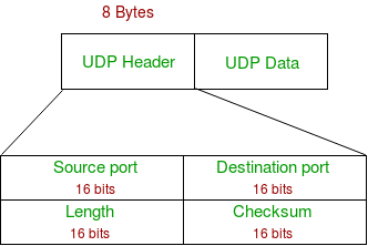
- ****UDP Header :**The UDP header is a simple 8-byte structure in the Transport Layer, containing four fields: Source Port, Destination Port, Length, and Checksum
**Difference between TCP and UDP
| TCP (Transmission Control Protocol) | UDP (User Datagram Protocol) |
|---|---|
| Connection-oriented protocol | Connectionless protocol |
| Reliable data delivery using acknowledgments and retransmissions | Unreliable data delivery (no acknowledgments) |
| Ensures in-order delivery using sequence numbers | No guarantee of packet order |
| Uses checksum, ACKs, and retransmission | Uses checksum only (optional in IPv4) |
| Supported using sliding window mechanism | Not supported |
| Implemented using Slow Start, Congestion Avoidance, Fast Retransmit | Not supported |
| Slower due to overhead | Faster due to minimal overhead |
| Minimum 20 bytes | Fixed 8 bytes |
| Uses 3-way handshake (SYN, SYN-ACK, ACK) | No handshake |
| Byte-stream oriented | Message-oriented |
| Detects and retransmits lost packets | Lost packets are not recovered |
| High overhead due to control mechanisms | Low overhead |
| HTTP, HTTPS, FTP, SMTP, SSH | DNS, VoIP, Video Streaming, Online Games |
**Session Layer
The Session Layer is the 5th layer of the OSI model. Its primary role is to establish, manage, and terminate sessions between two communicating devices.
A session refers to a logical connection that exists for the duration of communication.
**Why the Session Layer Is Needed
While the Transport Layer ensures reliable data transfer, the Session Layer manages the dialog itself:
- Who starts communication
- How long communication lasts
- When to pause, resume, or terminate communication
**Key Functions of the Session Layer
**Session Establishment
- Initializes a session between two network entities.
- Defines session parameters such as: Authentication, Authorization & Session ID
- Example: Logging into a remote server.
**Session Maintenance
- Keeps the session active during data exchange.
- Ensures that communication continues smoothly for the entire session duration.
- Manages session checkpoints and controls data flow.
**Session Termination
- Gracefully closes the session once communication is complete.
- Frees resources allocated to the session.
- Prevents unauthorized reuse of session data.
**Synchronization
- Adds synchronization points (checkpoints) into the data stream.
- If a failure occurs, communication can resume from the last checkpoint, not from the beginning.
- Very useful in long data transfers.
**Session Identification
- Identifies entities participating in a session.
- Uses session identifiers to track ongoing communication.
- Helps differentiate between multiple sessions from the same user or device.
**Presentation Layer
The Presentation Layer is the 6th layer of the OSI model. Its primary role is to prepare data for the Application Layer by ensuring that information sent from one system can be understood by another system, regardless of differences in data format, encoding, or security mechanisms.
In simple terms, this layer acts as a translator and formatter for network data.
**Why the Presentation Layer Is Needed
Different systems may use:
- Different data formats
- Different character encoding schemes
- Different encryption standards
The Presentation Layer ensures compatibility and interoperability between these systems.
**Key Functions of the Presentation Layer
**Data Translation (Format Conversion)
- Converts data from the sender’s format into a common network format.
- At the receiver side, it converts data back into the receiver’s format.
- Enables communication between heterogeneous systems.
**Examples
- ASCII ↔ Unicode
- EBCDIC ↔ ASCII
- Little-endian ↔ Big-endian
**Character Encoding
- Defines how characters are represented in binary form.
- Ensures correct interpretation of text data.
**Common encoding schemes
- ASCII
- Unicode
- UTF-8
- UTF-16
**Data Encryption and Decryption
- Protects data from unauthorized access.
- **Encryption at the sender side converts plaintext into ciphertext.
- **Decryption at the receiver side converts ciphertext back into readable data.
**Used for
- Data confidentiality
- Secure communication (e.g., SSL/TLS)
**Data Compression and Decompression
- Reduces the size of data before transmission.
- Improves bandwidth utilization and transmission speed.
- Decompression restores the original data at the receiver.
**Types
- Lossless compression (e.g., ZIP, PNG)
- Lossy compression (e.g., JPEG, MP3)
Application Layer
The Application Layer is the topmost layer of the OSI model and provides network services directly to end-user applications. It enables users and software applications to access network resources, exchange data, and perform communication tasks such as email, file transfer, and web browsing.
The Application Layer does not include the user interface itself, but it provides services used by applications like browsers, email clients, and FTP clients.
**Functions of Application Layer
**Network Resource Access : It Allows users to access remote resources such as
- Files
- Printers
- Web servers
Supports services like file sharing and directory access.
**Email Services
- Enables sending, receiving, and managing emails.
- Supports protocols for mail transfer, retrieval and synchronization.
**File Transfer and Management
- Supports uploading, downloading, and managing files on remote systems.
- Ensures controlled and reliable file exchange.
**Name Resolution
- Translates human-readable names into machine-readable addresses.
- Makes the internet user-friendly.
**Application-Level Communication
- Enables communication between client and server applications.
- Supports request–response mechanisms.
TCP/IP Model
The TCP/IP model is a practical and implementation-oriented networking model used in real-world networks, including the Internet. It was developed by DARPA (Defense Advanced Research Projects Agency) and forms the foundation of modern data communication.
Unlike the OSI model (7 layers), the TCP/IP model consists of 4 layers, each responsible for a specific set of networking functions.
Layers of TCP/IP Model
- Application Layer
- Transport Layer
- Internet Layer
- Network Access Layer
Application Layer in TCP/IP Model
The Application Layer is the topmost layer of the TCP/IP model. It provides network services directly to user applications and enables communication between software applications over a network.
In the TCP/IP model, this layer combines the responsibilities of three OSI layers:
- Application Layer (OSI Layer 7)
- Presentation Layer (OSI Layer 6)
- Session Layer (OSI Layer 5)
Key Functions
**User-Level Network Services
- Enables applications to access network resources
- Supports web browsing, email, file transfer, and remote login
**Data Representation and Formatting: It handles
- Data translation
- Character encoding
- Data compression
- Encryption and decryption
**Session Management
- Establishes, maintains, and terminates communication sessions
- Supports synchronization and dialog control
**Name Resolution
- Converts domain names into IP addresses
- Makes network usage human-friendly
**Application Communication
- Enables client–server interaction
- Supports request–response and message-based communication
Features of Application Layer (TCP/IP)
- Closest layer to the user
- Protocol-oriented
- Platform-independent
- Supports multiple application services
- Does not handle packet delivery or routing
Transport Layer in TCP/IP Model
The Transport Layer is the second layer of the TCP/IP model. It is responsible for end-to-end (process-to-process) communication between applications running on different hosts.
It ensures that data sent from a source application is delivered to the correct destination application reliably or efficiently, depending on the protocol used.
Key Functions of the Transport Layer
**Process-to-Process Communication
- Uses port numbers to identify source and destination applications.
- Enables multiple applications to communicate simultaneously on the same host.
**Segmentation and Reassembly
- Breaks large data into smaller units called segments.
- Reassembles segments at the receiver side.
**Multiplexing and Demultiplexing
- **Multiplexing: Multiple applications send data using a single network connection.
- **Demultiplexing: Data is delivered to the correct application using port numbers.
**Flow Control
- Ensures the sender does not exceed the receiver’s processing capacity.
- Uses sliding window mechanism (in TCP).
**Error Control
- Detects errors using checksums.
- Retransmits lost or corrupted data (TCP).
**Congestion Control
- Adjusts data transmission rate based on network congestion.
- Prevents network overload.
Internet Layer in TCP/IP Model
The Internet Layer is the third layer of the TCP/IP model. It is responsible for logical addressing, packet routing, and delivery of data across interconnected networks.
This layer determines how packets move from the source host to the destination host, even if both are on different networks.
**Key Functions
**Logical Addressing
- Assigns IP addresses to devices.
- Ensures unique identification of hosts across networks.
- Supports IPv4 (32-bit) and IPv6 (128-bit) addressing.
**Packet Routing
- Determines the best path from source to destination.
- Uses routing algorithms and routing tables in routers.
**Packet Forwarding
- Moves packets from one router to the next until they reach the destination.
- Uses next-hop routing.
**Fragmentation and Reassembly
- Breaks large packets into smaller fragments to match MTU size.
- Reassembles fragments at the destination host.
**Error Reporting and Diagnostics
Reports network-level errors such as:
- Destination unreachable
- Time exceeded
- Helps in network troubleshooting.
**Network Access Layer in TCP/IP Model
The Network Access Layer is the lowest layer of the TCP/IP model. It is responsible for physical transmission of data over the network medium and defines how data is placed onto and received from the physical network.
This layer combines the functionalities of the Data Link Layer and Physical Layer of the OSI model.
Key Functions
**Framing
Encapsulates IP packets into **frames
**Adds:
- Source MAC address
- Destination MAC address
- Error detection information
**Physical Addressing (MAC Addressing)
- Uses MAC addresses (48-bit) for local delivery.
- Ensures correct delivery within a LAN.
**Media Access Control
- Determines how devices share a common transmission medium.
- Prevents or manages collisions.
**Examples:
- CSMA/CD (Ethernet)
- CSMA/CA (Wi-Fi)
**Error Detection
Detects transmission errors using mechanisms like:
- CRC (Cyclic Redundancy Check)
Error correction is **not performed at this layer.
**Bit Transmission
Converts frames into binary signals (bits).
**Defines:
- Voltage levels
- Data rate
- Transmission mode
Difference Between OSI Model and TCP/IP Model
| OSI Model | TCP/IP Model |
|---|---|
| Open Systems Interconnection | Transmission Control Protocol / Internet Protocol |
| ISO (International Organization for Standardization) | DARPA (U.S. Department of Defense) |
| 7 layers | 4 layers |
| Conceptual and theoretical model | Practical and implementation-based model |
| Strict layered architecture | Flexible layered architecture |
| Protocol-independent | Protocol-oriented |
| Supports only connection-oriented service | Supports both TCP (reliable) and UDP (unreliable) |
| Supports both connection-oriented and connectionless services | Supports only connectionless service (IP) |
| Implemented at Transport Layer | Implemented mainly by TCP |
| Separate layers | Combined into Application Layer |
| Data Link and Transport layers | Transport layer (TCP) |
| Defined in Network Layer | Defined in Internet Layer |
| Educational and reference model | Used in real-world networks (Internet) |
| Rarely implemented fully | Widely implemented (Internet) |
**Common Network Protocols: Ports, Layers, and Functions
| Protocol (Port Number) | OSI / TCP-IP Layer | Work / Function |
|---|---|---|
| HTTP (80) | Application | Transfers web pages using request–response model |
| HTTPS (443) | Application | Secure web communication using encryption (TLS/SSL) |
| FTP (21 control, 20 data) | Application | Transfers files between client and server |
| SMTP (25) | Application | Sends emails between mail servers |
| IMAP (143) | Application | Accesses and synchronizes emails on server |
| DNS (53 UDP/TCP) | Application | Resolves domain names to IP addresses |
| Telnet (23) | Application | Remote login (unencrypted) |
| SSH (22) | Application | Secure remote login and command execution |
| SNMP (161/162) | Application | Network monitoring and management |
| DHCP (67 server, 68 client) | Application | Automatically assigns IP configuration |
| TCP | Transport | Reliable, ordered, connection-oriented data delivery |
| UDP | Transport | Fast, connectionless data delivery |
| IP | Internet / Network | Logical addressing and packet routing |
| ICMP | Internet / Network | Error reporting and diagnostics |
| ARP | Internet / Network | Maps IP address to MAC address |
| Ethernet | Data Link / Network Access | Framing and MAC-based delivery |
| Wi-Fi / 802.11 | Data Link / Network Access | Wireless LAN communication |
Network Devices
Network Devices are hardware components used to connect, manage, control, and communicate data between computers and other devices within a network. They enable data transmission, routing, security, and network management.
See Last Minute Notes on all subjects here.