fiber Bragg gratings (original) (raw)
Acronym: FBG
Definition: reflective structures in the core of an optical fiber with a periodic or aperiodic perturbation of the effective refractive index
Categories:  fiber optics and waveguides,
  photonic devices
-
- Bragg gratings
* holographic bulk gratings
* ruled bulk gratings
* volume Bragg gratings
* fiber Bragg gratings
- Bragg gratings
-
- fiber optics
* fibers
* fiber connectors
* fiber-optic adapters
* fiber couplers
* fiber-optic pump combiners
* fiber bundles
* fiber endface inspection
* cleaving of fibers
* fiber cleavers
* fiber joints
* fiber splices
* fiber Bragg gratings
* fiber cables
* fiber coatings
* fiber strippers
* fiber recoaters
* fiber coils
* fiber collimators
* fiber launch systems
* fiber lenses
* fiber loop mirrors
* fiber patch panels
* fiber shuffles
* fiber-optic attenuators
* fiber-optic plates
* fiber-optic tapers
* (more topics)
- fiber optics
Related: Bragg gratingsvolume Bragg gratingsfibersfiber-optic sensorsoptical temperature sensorsoptical strain sensorsdistributed feedback laserspulse stretchers
Page views in 12 months: 7623
DOI: 10.61835/73v Cite the article: BibTex BibLaTex plain textHTML Link to this page! LinkedIn
Content quality and neutrality are maintained according to our editorial policy.
📦 For purchasing fiber Bragg gratings, use the RP Photonics Buyer's Guide — an expert-curated directory for finding all relevant suppliers, which also offers advanced purchasing assistance.
Contents
What is a Fiber Bragg Grating?
A fiber Bragg grating is a periodic or aperiodic perturbation of the effective refractive index in the core of an optical fiber (see Figure 1). Typically, the perturbation is approximately periodic over a certain length of e.g. a few millimeters or centimeters, and the period is of the order of hundreds of nanometers, or much longer than that for long-period fiber gratings (see below).
For short periods of the index modulation, the refractive index perturbation leads to the reflection of light (propagating along the fiber) in a narrow range of wavelengths, for which a Bragg condition is satisfied (→ Bragg mirrors): \frac{{2\pi }}{\Lambda } = 2 \cdot \frac{{2\pi \: {n_{{\rm{eff}}}}}}{\lambda }\quad \Rightarrow \quad \lambda = 2 \: {n_{{\rm{eff}}}} \: \Lambda
where ($\Lambda$) is the grating period, ($\lambda$) is the vacuum wavelength, and ($n_\rm{eff}$) is the effective refractive index of light in the fiber. Essentially, the condition means that the wavenumber of the grating matches the difference of the (opposite) wave vectors of the incident and reflected waves. In that case, the complex amplitudes corresponding to reflected field contributions from different parts of the grating are all in phase so that they can add up constructively; this is a kind of phase matching. Even a weak index modulation (with an amplitude of e.g. 10−4) is sufficient for achieving nearly total reflection, if the grating is sufficiently long (e.g. a few millimeters).

Figure 1: Schematic structure of a fiber Bragg grating (FBG). The fiber core has a periodically varying refractive index over some length. The drawing is not to scale; typical dimensions are 125 μm cladding diameter and 8 μm core diameter; periods of the refractive index gratings vary in the range of hundreds of nanometers or (for long-period gratings) hundreds of micrometers.
Light at other wavelengths, not satisfying the Bragg condition, is almost unaffected by the Bragg grating, except for some side lobes which frequently occur in the reflection spectrum (but can be suppressed by apodization of the grating, see below).
The reflection bandwidth of a fiber grating, which is typically well below 1 nm, depends on both the length and the strength of the refractive index modulation. The narrowest bandwidth values, as are desirable e.g. for the construction of single-frequency fiber lasers or for certain optical filters, are obtained for long gratings with weak index modulation. Large bandwidths may be achieved with short and strong gratings, but also with aperiodic designs of longer length (see below).
As the wavelength of maximum reflectance depends not only on the Bragg grating period but also on temperature and mechanical strain, Bragg gratings can be used in temperature and strain sensors. Transverse stress, as generated e.g. by squeezing a fiber grating between two flat plates, induces birefringence and thus polarization-dependent Bragg wavelengths.
Physical Modeling of the Optical Properties
Most fiber Bragg gratings are used in single-mode fibers, and in that case the physical modeling is often relatively simple. One may use a model based on mode coupling, leading to a pair of differential equations with a coupling term, the magnitude of which is related to the local strength of the index modulation. The coupling is then effectively assumed to be smoothly distributed, and the numerical integration is done with a step size which may be much larger than the grating period.
Such methods can be used for calculating the frequency-dependent complex amplitudes for transmission and reflection of light. These reveal not only the fractions of reflected and transmitted power, but also (via numerical differentiation) the chromatic dispersion.
Numerical models become substantially more complicated if many propagation modes are involved. Even for a single-mode fiber, it may be necessary to consider four modes (rather than just two counterpropagating modes) if birefringence is relevant, or even with a larger number of modes if coupling to cladding modes can occur. For multimode fibers, a multitude of core modes has to be accounted for. In such cases, the coupling coefficients depend not only on the amplitude of the index modulation, but also on the three-dimensional shape of the grating.

Figure 2: Reflectance spectra of a 5.4 mm long FBG with different refractive index contrast, corresponding to different times of exposure to UV light. The side lobes of the reflectance curve, as observed for a high index contrast, could be removed by apodization, i.e., by reducing the index contrast towards the ends of the grating. The calculations have been made with the software RP Coating.
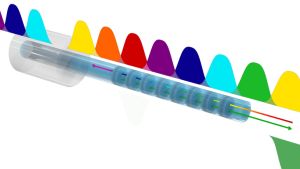
It is also possible to apply numerical beam propagation techniques for the analysis of fiber Bragg gratings. This is particularly the case when there are no reflections, but only coupling between modes propagating in essentially the same direction — a typical situation for long-period Bragg gratings (with grating periods of the order of 1 mm, for example). (For cases involving counterpropagating modes, beam propagation methods are much more difficult to apply.) Figure 3 shows an example — the case of a long-period fiber Bragg grating where the poling period has been chosen such that effective coupling from the fundamental mode to the LP03 mode is possible. Advantages of the fully numerical technique are that no complicated analytical calculations are required and that the typically involved simplifications of an analytical model (which may or may not be justified in practice) can be avoided.

Figure 3: Intensity distribution inside a fiber Bragg grating. The red and blue curve shows the evolution of optical power in the LP03 mode and LP01 mode, respectively. This diagram has been taken from a case study on numerical beam propagation in fiber devices.
Special Types of Gratings
Apodized Gratings
If the strength of the index modulation in a grating is constant over some length, and suddenly drops to zero outside that range, the reflection spectrum exhibits side lobes, in particular if the peak reflectance is high (see Figure 2). These side lobes are sometimes disturbing, e.g. in some applications of fiber Bragg gratings as optical filters. They can be largely removed with the technique of apodization: the strength of the index modulation is smoothly ramped up and down along the grating. Of course, one then needs an increased overall length of the grating to achieve a certain peak reflectance. For the exact profile of the index modulation in an apodized fiber Bragg grating, there is a trade-off between optimum side-lobe suppression and maximum reflectance for some restricted grating length and a given maximum strength of index modulation.
Gratings with Aperiodic Index Modulation (Chirped Gratings)
Fiber gratings with aperiodic index modulation can have interesting properties, such as reflectance curves without side lobes, multiple tailored reflection bands, or special chromatic dispersion profiles. Particularly for dispersion compensation, so-called chirped fiber gratings are used [28], where the Bragg wavelength monotonously varies with position. It is possible e.g. to achieve very large group delay dispersion in a moderate length of fiber, sufficient for compensating the dispersion of a long span of transmission fiber in an optical fiber communications system. Another application is pulse compression, e.g. within a chirped-pulse amplifier system.
Chirped fiber gratings are also interesting for application as distributed fiber-optic sensors with intragrating sensing, i.e., monitoring e.g. the temperature along the length of the device.
Tilted Fiber Bragg Gratings
Some fiber Bragg gratings are fabricated such that the planes of constant refractive index are not normal to the fiber axis, as usual, but are tilted against the axis by some angle (often a few degrees). If that tilt is strong enough, the coupling to backward core modes may become quite weak; instead, one has a coupling of core modes to cladding modes. Effectively, one obtains a transmission loss without the corresponding reflection into the core. That can be used for a notch filter, attenuating light in a certain spectral region, which may be widened if the grating is chirped at the same time. An application of this can be the reduction of stimulated Raman scattering in high-power fiber lasers and amplifiers [33, 34], for example.
Long-period Bragg Gratings
Typical FBGs have grating periods of a few hundred nanometers, coupling counterpropagating waves in the core. A second possibility is to use long-period Bragg gratings (LPG) [19] with periods of the order of hundreds of microns or more (often with tilted grating planes) and a length of e.g. a few centimeters.
Such gratings can only couple modes with the same propagation direction because the difference of wavevectors for counterpropagating waves would be too large to be matched by the grating. For example, the fundamental mode of a multimode fiber can be coupled to a certain higher-order mode, or a core mode can be coupled to cladding modes propagating in a similar direction. In the latter case, the coupling effectively introduces propagation losses because light in cladding modes normally experiences strong losses in the fiber coating.
Long-period gratings can even be made by pressing a short length of fiber against a plate with periodic grooves [18]. This kind of grating is reversible and potentially tunable.
Long-period gratings are used for introducing carefully controlled wavelength-dependent losses, e.g. for gain equalization in erbium-doped fiber amplifiers or for suppressing effects of stimulated Raman scattering, but are also used for fiber-optic sensors.
Fiber Gratings in Polymer Fibers
It is also possible to write FBGs in polymer optical fibers. As with silica fibers, one usually uses ultraviolet light, but the physical mechanisms are somewhat different. An advantage of Bragg gratings in polymer fibers is the larger wavelength tunability: polymer fibers can be stretched more strongly, and they react more strongly to temperature changes.
Bragg Gratings in Multimode and Multi-core Fibers
It is possible to fabricate Bragg gratings in multimode fibers. However, a substantial problem for various applications is that the Bragg condition depends on the involved fiber modes, which generally have different propagation constants. Therefore, the wavelength of maximum reflectance is generally different between different modes. That is a substantial impediment for the use of FBGs in multimode fibers. For obtaining high reflectance for all guided modes at a certain wavelength, one can use a chirped (and correspondingly longer) Bragg grating, but generally the multimode nature of a fiber imposes substantial restrictions.
Some applications (like filtering of star light in astronomical telescopes) require multimode fibers but cannot tolerate mode-dependent reflections. A solution which has been developed for such applications are photonic lanterns, allowing one to send the light into a number of single-mode fibers, where Bragg gratings perform well, and later back to a multimode fiber. The lantern principle also works with other kinds of waveguides, in particular with multi-core fibers. Fortunately, it is possible with carefully optimized methods to write rather uniform Bragg gratings even into multi-core fibers with a large core count [31].
Fabrication of Fiber Bragg Gratings
The fabrication of fiber Bragg gratings typically involves the illumination of the core material with ultraviolet laser light (e.g. from a KrF or ArF excimer laser or other type of ultraviolet laser), which induces some structural changes and thus a permanent modification of the refractive index. The photosensitivity of the core glass is strongly dependent on the chemical composition and the UV wavelength: silica glass (as is often used for the cladding) has a very weak photosensitivity, whereas germanosilicate glass exhibits a much stronger effect, making possible a refractive index contrast up to ≈ 10−3. A significant further increase in photosensitivity is possible by loading the fiber with hydrogen (hydrogenated fibers). For that purpose, the fiber is kept in a high-pressure hydrogen atmosphere for some time. Another possibility is to use boron co-doped fibers.
Phosphate glasses are normally regarded as unsuitable for FBG fabrication, but special methods make this possible [26].
The first fiber Bragg gratings [1] were fabricated with a visible laser beam propagating along the fiber core, but in 1989 a more versatile technique was demonstrated by G. Meltz et al. [3], using the interferometric superposition of ultraviolet beams which come from the side of the fiber (transverse holographic technique). The angle between the ultraviolet beams determines the period of the light pattern in the fiber core and thus the Bragg wavelength. The two ultraviolet beams are often generated by exposing a periodic phase mask (photomask) with a single UV beam [4] (phase mask technique), using the two first-order diffracted beams. Non-periodic phase masks can be used to obtain more complicated patterns. Another technique is the point-by-point technique [22, 30], where the regions with increased refractive index are written point by point with a small focused laser beam. This is an appropriate (and very flexible) technique particularly for long-period Bragg gratings (see above), although extra propagation loss may occur at shorter wavelengths.
Instead of ultraviolet light, infrared light in the form of intense femtosecond pulses can also be used for writing Bragg gratings [20] in various kinds of glasses. In that case, two-photon absorption essentially occurs only near the focus of the laser beam. It is even possible to write such gratings through the polymer coating of a fiber [24], since the intensity in the coating is much lower when the beam is focused on the fiber core. A totally different method also using infrared light is the fabrication of long-period FBGs in photonic crystal fibers by irradiation with a CO2 laser beam.
Depending on the writing conditions, there are actually different physical mechanisms involved in the Bragg grating formation, and one distinguishes different types of gratings. Type I gratings are written with moderate intensities and exhibit an index grating right across the core. Type II gratings [5] can be written with much higher intensities within very short times, often with a single nanosecond pulse from an excimer laser (single-shot damage gratings). They can be written on the drawing tower [6] just before the fiber is coated, so that one avoids the process of removing an already fabricated coating, and obtains a grating with the full mechanical strength of ordinary fiber.
Chirped gratings can be obtained in different ways, e.g. with point-to-point laser inscribing, with chirped phase masks or by tapering the fiber after writing the grating.
Fiber Bragg gratings are fairly durable, but the degree of durability (e.g. the temperature at which the grating may be erased) depends strongly on the fiber material and the details of grating fabrication. The optical properties may change during some time after fabrication, before they settle at their final values. To reach a stable state more quickly, an annealing procedure can be applied, which typically means that the fiber is kept at some elevated temperature for a few hours.
Applications of Fiber Bragg Gratings
Telecom applications of FBGs often involve wavelength filtering, e.g. for combining or separating multiple wavelength channels in wavelength division multiplexing systems (add–drop multiplexers). Extremely narrow-band filters can be realized e.g. with long FBGs (having a length of up to about a meter, see Ref. [32]) or with combinations of such gratings. There are also shorter FBGs with tunable center wavelength, e.g. via variable mechanical strain applied with a piezo transducer. With such technology one can realize tunable optical filters.
FBGs with strong chromatic dispersion can be used for dispersion compensation and for pulse stretching in chirped-pulse amplification systems.
FBGs can be used as end mirrors of fiber lasers (→ distributed Bragg reflector lasers, DBR fiber lasers), then typically restricting the emission to a very narrow spectral range. Even single-frequency operation can be achieved e.g. by having the whole laser resonator formed by an FBG with a phase shift in the middle (→ distributed feedback lasers).
Outside a laser resonator, an FBG can serve as a wavelength reference e.g. for stabilization of the laser wavelength. This method can also be applied for wavelength-stabilized laser diodes. (See also the article on frequency-stabilized lasers.)
If the polarization of the writing beams is perpendicular to the fiber axis, there can be a significant deviation between the Bragg wavelengths for both polarization directions (i.e. a birefringence). This may be used e.g. for fabricating rocking filters.
Another field of application fiber-optic sensors, for example for strain or temperature, where one exploits the influence of strain or temperature on the optical properties of gratings.
The range of interesting phenomena in FBGs is further enriched by the occurrence of optical nonlinearities at higher optical power levels.
Case Study
The following case study is available, which discusses some aspects of fiber Bragg gratings:
- Fiber Bragg grating for coupling into higher-order modes
- We simulate a long-period grating in a multimode fiber, which can efficiently couple light from the fundamental mode to a specific higher-order mode.
Frequently Asked Questions
What is a fiber Bragg grating (FBG)?
A fiber Bragg grating is a structure within the core of an optical fiber with a periodic variation of the refractive index. It acts as a wavelength-selective mirror, reflecting light in a narrow range of wavelengths while transmitting others.
How does a fiber Bragg grating work?
An FBG reflects light when the Bragg condition ($\lambda = 2 \: n_{eff} \: \Lambda$) is met. At this wavelength, reflections from each part of the grating add up constructively. Light at other wavelengths is transmitted through the grating largely unaffected.
How are fiber Bragg gratings fabricated?
FBGs are typically made by exposing the core of a photosensitive fiber to an interference pattern of intense ultraviolet laser light. This process creates a permanent, periodic modulation of the core's refractive index.
What are the main applications of fiber Bragg gratings?
FBGs are widely used in telecommunications for wavelength filtering and dispersion compensation. They also serve as key components in fiber lasers and are extensively used to build fiber-optic sensors for measuring temperature and strain.
What is a chirped fiber Bragg grating?
A chirped fiber Bragg grating is a grating where the period of the index modulation varies continuously along its length. This design is used for applications like compensating chromatic dispersion in fiber-optic communications or for stretching and compressing optical pulses.
What is the purpose of apodization in a fiber Bragg grating?
Apodization, where the strength of the index modulation smoothly decreases towards the ends of the grating, is used to suppress unwanted side lobes in the reflection spectrum. This results in a cleaner filter response.
What is the difference between a standard FBG and a long-period grating?
A standard FBG has a short period (hundreds of nanometers) and reflects a narrow band of wavelengths. A long-period grating has a much larger period (hundreds of micrometers) and couples light between co-propagating modes, creating a wavelength-dependent loss filter.
How can a fiber Bragg grating be used as a sensor?
The wavelength reflected by an FBG is sensitive to changes in temperature and mechanical strain, as these affect the grating period and the fiber's refractive index. By precisely measuring the reflected wavelength, an FBG can function as a sensor for these physical quantities.
Suppliers
Sponsored content: The RP Photonics Buyer's Guide contains 45 suppliers for fiber Bragg gratings. Among them:

⚙ hardware
Serving North America, RPMC offers a selection of Fiber Bragg Grating Laser configurations and options. These ultra-stable, fiber-coupled devices feature single-frequency operation, >0.5 km coherence length and excellent SMSR (50 dB), outperforming standard DFB devices in wavelength stability (±1 pm) and low noise (RIN <-140 dB/Hz).
These configurable & fully customizable FBG devices provide center wavelength options around 1260 nm, 1383 nm, 1550 nm, 1648 nm, 1653 nm, and 1665 nm, linewidths from <200 kHz to <3 kHz, CW output power up to 10 mW (up to 50 mW in pulsed operation), and come standard in a cooled 14-pin butterfly package, ensuring reliable, stable operation.
Our narrow linewidth FBG lasers deliver exceptional wavelength stability and low noise, making them a trusted choice for sensing and telecom applications, ensuring robust performance and seamless integration.
Let RPMC help you find the right laser today!

⚙ hardware
Based on the Fiber Bragg Grating (FBG) technology and the newLight optical sensor series, the FS70 configurable arrays are optical fibers with multiple FBGs and high-performance coatings. These are optimally suited for multipoint measurement of strain in laboratories and in all kinds of industries.

⚙ hardware

Femtika produces FBG Laser Workstations for precise Fiber Bragg Grating (FBG) inscription for optical sensing applications.
The machine support a range of inscription techniques — Point-by-Point (PbP), Line-by-Line (LbL), and phase mask writing — offering full control over grating geometry, pitch, and positioning.
Other features include:
- Fiber core detection using camera or autofocus
- 4 core fiber writing
- Cladding removal via laser ablation
- Comprehensive laser control capabilities for the precise optimization of specialized tasks
- Automation possibility with a roll-to-roll solution (also available with an immersive objective
The photo represents the reflection spectrum of a fiber Bragg granting inscribed through the fiber coating using the line-to-line technique. Measurement performed using Componous interrogator.

⚙ hardware
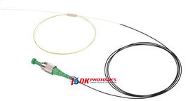
DK Photonics offers fiber Bragg gratings for a wide range of applications in the areas of telecommunications, lasers and sensors. With excellent apodized technologies, we can offer high quality FBGs meeting different requirements of our customers.

⚙ hardware

FFA-01 is a fiber array sensor with configurable number of FBG elements and their spacing over the fiber length. FFA-01 is typically used for direct gluing to the measured surface to capture strain changes of the monitored structure.

⚙ hardware
In order for fiber Bragg gratings to function properly and for the optical signals to be reliable, it is essential that the FBGs are equipped with the connector types that are appropriate for the respective situation. When selecting the correct connector type, the mechanical stress and optical requirements must be taken into account.
Diamond can fall back on its extensive knowledge in the field of FBG sensor assemblies as well as in the development and manufacturing of sensor packaging, thus offering a wide range of ideal solutions for your requirements.

⚙ hardware

Mastering advanced FBG writing technologies with holographic phase mask and e-beam phase mask, O/E Land can produce many different types of fiber Bragg gratings with different types of packaging. We have full license for the CRC/UTC Fiber Bragg Grating Technologies Portfolio, and have a vast inventory of fiber gratings.
O/E LAND INC. has also developed a strong expertise in the writing of multi-grating arrays with 2, 3, 4, 6 or up to 16 fiber gratings in a single fiber, with no need for splicing. Fiber Bragg grating arrays can be used in DWDM, CWDM optical systems to add or drop multiple channels simultaneously, and in sensors and for instrumentation purposes.
Bibliography
| [1] | K. O. Hill et al., “Photosensitivity in optical fiber waveguides: application to reflection fiber fabrication”, Appl. Phys. Lett. 32, 647 (1978); doi:10.1063/1.89881 |
|---|---|
| [2] | F. Ouellette, “Dispersion cancellation using linearly chirped Bragg grating filters in optical waveguides”, Opt. Lett. 12 (10), 847 (1987); doi:10.1364/OL.12.000847 |
| [3] | G. Meltz et al., “Formation of Bragg gratings in optical fibers by a transverse holographic method”, Opt. Lett. 14 (15), 823 (1989); doi:10.1364/OL.14.000823 |
| [4] | K. O. Hill, “Bragg grating fabricated in monomode photosensitive optical fiber by UV exposure through a phase mask”, Appl. Phys. Lett. 62 (10), 1035 (1993); doi:10.1063/1.108786 |
| [5] | J. L. Archambault et al., “100% reflectivity Bragg reflectors produced in optical fibres by single excimer laser pulses”, Electron. Lett. 29, 453 (1993); doi:10.1049/el:19930303 |
| [6] | L. Dong et al., “Single-pulse Bragg gratings written during fibre drawing”, Electron. Lett. 29 (17), 1577 (1993); doi:10.1049/el:19931051 |
| [7] | R. Kashyap, “Photosensitive optical fibers: devices and applications”, Opt. Fiber Technol. 1, 17 (1994); doi:10.1006/ofte.1994.1003 |
| [8] | H. Patrick et al., “Annealing of Bragg gratings in hydrogen-loaded optical fiber”, J. Appl. Phys. 78 (5), 2940 (1995); doi:10.1063/1.360753 |
| [9] | I. Bennion et al., “Tutorial review, UV-written in-fiber Bragg gratings”, Opt. Quantum Electron. 28, 93 (1996); doi:10.1007/BF00278281 |
| [10] | A. D. Kersey, “A review on recent developments in fiber optic sensor technology”, Opt. Fiber Technol. 2, 291 (1996); doi:10.1006/ofte.1996.0036 |
| [11] | K. O. Hill and G. Meltz, “Fiber Bragg grating technology – fundamentals and overview”, IEEE J. Lightwave Technol. 15 (8), 1263 (1997); doi:10.1109/50.618320 |
| [12] | L. Dong and W. F. Liu, “Thermal decay of fiber Bragg gratings of positive and negative index changes formed at 193 nm in a boron-codoped germanosilicate fiber”, Appl. Opt. 36 (31), 8222 (1997); doi:10.1364/AO.36.008222 |
| [13] | L. Dong et al., “Efficient single-frequency fiber lasers with novel photosensitive Er/Yb optical fibers”, Opt. Lett. 22 (10), 694 (1997); doi:10.1364/OL.22.000694 |
| [14] | A. D. Kersey et al., “Fiber grating sensors”, IEEE J. Lightwave Technol. 15 (8), 1442 (1997); doi:10.1109/50.618377 |
| [15] | T. Erdogan, “Fiber grating spectra”, IEEE J. Lightwave Technol. 15 (8), 1277 (1997); doi:10.1109/50.618322 |
| [16] | B.-O. Guan et al., “Highly stable fiber Bragg gratings written in hydrogen-loaded fiber”, IEEE Photon. Technol. Lett. 12 (10), 1349 (2000); doi:10.1109/68.883826 |
| [17] | T. Mizunami et al., “Bragg gratings in multimode and few-mode optical fibers”, J. Lightwave Technol. 18 (2), 230 (2000); doi:10.1109/50.822797 |
| [18] | S. Savin et al., “Tunable mechanically induced long-period fiber gratings”, Opt. Lett. 25 (10), 710 (2000); doi:10.1364/OL.25.000710 |
| [19] | M. Harurnoto et al., “Gain-flattening filter using long-period fiber gratings”, J. Lightwave Technol. 20 (6), 1027 (2002); doi:10.1109/JLT.2002.1018814 |
| [20] | S. J. Mihailov et al., “Fiber Bragg gratings made with a phase mask and 800-nm femtosecond radiation”, Opt. Lett. 28 (12), 995 (2003); doi:10.1364/OL.28.000995 |
| [21] | A. Dragomir et al., “Inscription of fiber Bragg gratings by ultraviolet femtosecond radiation”, Opt. Lett. 28 (22), 2171 (2003); doi:10.1364/OL.28.002171 |
| [22] | A. Martinez et al., “Thermal properties of fibre Bragg gratings inscribed point-by-point by infrared femtosecond laser”, Electron. Lett. 41 (4), 176 (2005); doi:10.1049/el:20057898 |
| [23] | M. Sumetsky and B. J. Eggleton, “Fiber Bragg gratings for dispersion compensation in optical communication systems”, J. Opt. Fiber Commun. Rep. 2, 256-278 (2005); doi:10.1007/s10297-004-0026-9 |
| [24] | A. Martinez et al., “Direct inscription of Bragg gratings in coated fibers by an infrared femtosecond laser”, Opt. Lett. 31 (11), 1603 (2006); doi:10.1364/OL.31.001603 |
| [25] | E. Wikszak et al., “Erbium fiber laser based on intracore femtosecond-written fiber Bragg grating”, Opt. Lett. 31 (16), 2390 (2006); doi:10.1364/OL.31.002390 |
| [26] | J. Albert et al., “Strong Bragg gratings in phosphate glass single mode fiber”, Appl. Phys. Lett. 89, 101127 (2006); doi:10.1063/1.2349318 |
| [27] | G. Androz et al., “Monolithic fluoride-fiber laser at 1480 nm using fiber Bragg gratings”, Opt. Lett. 32 (10), 1302 (2007); doi:10.1364/OL.32.001302 |
| [28] | N. M. Litchinitser et al., “Fiber-based tunable dispersion compensation”, J. Opt. Fiber Commun. Rep. 4, 41 (2007); doi:10.1007/978-0-387-48948-3_11 |
| [29] | J. Canning, “Fibre gratings and devices for sensors and lasers”, Laser & Photon. Rev. 2 (4), 275 (2008); doi:10.1002/lpor.200810010 |
| [30] | G. D. Marshall et al., “Point-by-point written fiber-Bragg gratings and their application in complex grating designs”, Opt. Express 18 (19), 19844 (2010); doi:10.1364/OE.18.019844 |
| [31] | T. A. Birks et al., ““Photonic lantern” spectral filters in multi-core fibre”, Opt. Express 20 (13), 13996 (2012); doi:10.1364/OE.20.013996 |
| [32] | M. Gagné et al., “Fabrication of high quality, ultra-long fiber Bragg gratings: up to 2 million periods in phase”, Opt. Express 22 (1), 387 (2014); doi:10.1364/OE.22.000387 |
| [33] | M. Wang et al., “Fabrication of chirped and tilted fiber Bragg gratings and suppression of stimulated Raman scattering in fiber amplifiers”, Opt. Express 25 (2), 1529 (2017); doi:10.1364/OE.25.001529 |
| [34] | M. Heck et al., “Mitigation of stimulated Raman scattering in high power fiber lasers using transmission gratings”, Proc. SPIE 10512, 105121I (2018); doi:10.1117/12.2289511 |
| [35] | R. G. Krämer et al., “Femtosecond written fiber Bragg gratings in ytterbium-doped fibers for fiber lasers in the kilowatt regime”, Opt. Lett. 44 (4), 723 (2019); doi:10.1364/OL.44.000723 |
| [36] | T. O. Imogore et al., “Dispersion tailoring of femtosecond laser written chirped fiber Bragg gratings by selective femtosecond laser post-processing”, Opt. Lett. 45 (23), 6526 (2020); doi:10.1364/OL.411679 |
| [37] | X.-P. Pan et al., “Femtosecond laser inscribed chirped fiber Bragg gratings”, Opt. Lett. 46 (9), 2059 (2021); doi:10.1364/OL.422576 |
| [38] | J. He et al., “Femtosecond laser line-by-line inscription of apodized fiber Bragg gratings”, Opt. Lett. 46 (22), 5663 (2021); doi:10.1364/OL.441888 |
| [39] | R. Kashyap, Fiber Bragg Gratings, Academic Press, San Diego (1999) |
(Suggest additional literature!)
Questions and Comments from Users
Here you can submit questions and comments. As far as they get accepted by the author, they will appear above this paragraph together with the author’s answer. The author will decide on acceptance based on certain criteria. Essentially, the issue must be of sufficiently broad interest.
Please do not enter personal data here. (See also our privacy declaration.) If you wish to receive personal feedback or consultancy from the author, please contact him, e.g. via e-mail.
By submitting the information, you give your consent to the potential publication of your inputs on our website according to our rules. (If you later retract your consent, we will delete those inputs.) As your inputs are first reviewed by the author, they may be published with some delay.